


81
■
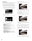
System Status Table
The table shows the system status in real time.
1. Select a desired monitor. (Refer to p. 56 Monitor
Selection.)
2. Display "SysStat" menu. (Refer to Step 1 and 2 of p. 77
To Recall Menu Functions.)
3. Select a desired function by pressing one of the F1 to
F3 buttons.
Available buttons and functions
F1: On
Opens the SYSTEM STATUS table.
F2: Off
Closes the SYSTEM STATUS table.
F3: Blk
Changes the monitor background beween camera
images and black picture.
MON: Monitor number
AREA: Area number
CAM/DVR/SEQ:
<Example>
C6400001: Unit 64, Camera 1
R6400001: Unit 64, Recorder 1
T640010001P: Unit 64, Area 1, Tour Sequence 1
pause
G640010001P: Unit 64, Area 1, Group Sequence 1
pause
DEV: Device Name
K: System controller number with normal user oper-
ator.
S: System controller number with super user opera-
tor.
ALM: Alarm
EVT: Timer event
USER: User ID
Note: Alarm USRID consists of alarm number and
alarm action number.
E.g. "ALM20" indicates alarm #2 and its action
#0.
PRI: User priority
4. To display the next page, press the + button.
To display the previous page, press the – button.
Notes:
• To display the first page of table, press the + but-
ton while holding down the SHIFT button.
• To display the last page of table, press the – button
while holding down the SHIFT button.
5. To exit the SYSTEM STATUS table, perform either of the
following.
• Select a camera. (Refer to p. 56 Camera Selection.)
• Press the MON(ESC) button.
• Press the EXIT button.
■
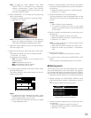
Video Loss History Table
There are 100 video loss detection records stored in
chronological order in 10 pages of table.
1. Select a desired monitor. (Refer to p. 56 Monitor
Selection.)
2. Display "VL Hist" menu. (Refer to Step 1 and 2 of p. 77
To Recall Menu Functions.)
3. Select a desired function by pressing one of the F1 to
F3 buttons.
Available buttons and functions
F1: On
Opens the VIDEO LOSS HISTORY table.
F2: Off
Closes the VIDEO LOSS HISTORY table.
F3: Blk
Changes the monitor background beween camera
images and black picture.
CAM: Logical camera number that is connected to the
system.
STATE: Indicates video loss changes.
OK: Video loss is recovered.
LS: Video level is below normal and in sync.
VL: Video level is below normal and out of sync.
HL: Video level is above normal and out of sync.
TYPE: Place where the video loss occurs.
S: Video crosspoint input (Not supported)
C: Camera control input
DATE/TIME: Date and time when the video loss state
changes.
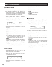
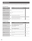
SysStat: 010
On Off Blk
SYSTEM STATUS PG
MON AREA CAM/DVR/SEQ DEV USER PRI
1 1 C6400001 K1 1 1
999 999 R6400001 S128 12345 1234
999 999 T640010001P S128 12345 999
999 999 G640010001P S128 12345 999
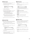
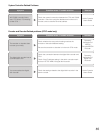
VL Hist: 011
On Off Blk
VIDEO LOSS HISTORY PG
CAM STATE TYPE DATE/TIME
6401 OK C 01/01/01 12:00