


43
Text appearing in blue is explanatory, and not part of the sys.ini file.
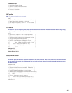
Interface section
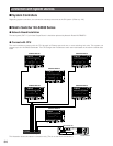
The CPU can incorporate up to three Ethernet network interface cards.
[INTERFACES]
***{ Number of interfaces in the system}
Numinterfaces=3
The number used here is the number of the Ethernet ports on MPU955A CPU.
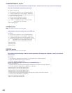
***{ Interface Definitions }
***{ Interface<Number>=<IPA>,<SUBNET MASK>,<BOOT SERVER IPA> }
***{ !! Note: The InterfaceX IPAs must match the MainX CPU }
***{ hardware settings in order for the System to }
***{ operate correctly!!
***{ MainA CPU }
In Standard System, the MPU955A CPU should use the IP addresses that follow. In this case, the {MainB
CPU}’s interface numbers should be commented with asterisks.
Interface0=192.168.200.200,255.255.255.0,192.168.200.200
Interface0 is an interface for GX devices. (NTSC model only)
Interface1=172.18.0.1,255.255.0.0,172.18.0.1
Interface1 is an interface for system controller.
Interface2=172.16.192.1,255.255.0.0,172.16.192.1
Interface2 is used for SNMP, SNTP feature. (Not currently supported)
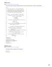
***{ MainB CPU }
In Redundant System, the second MPU955A CPU should use following IP addresses (remove the asterisks
below). In this case, {MainA CPU}’s interface numbers should be commented with asterisks.
*Interface0=192.168.200.201,255,255,255,0,192.168.200.201
*Interface1=172.18.0.2,255.255.0.0,172.18.0.2
*Interface2=172.16.192.2,255.255.0.0,172.16.192.2
Frames section
Note: This section does not apply to the MPU955A system, and should not be changed.
[FRAMES]
***{ MX Frame definition from Admin file }
***{ MXSW has format <num_rows>,<num_cols>,<interface_num> }
***{ All others use <num_functions>,<interface_num> }
***{ All 0's used for digital-only systems. }
MXSWFunction=0,0,0
MXCONTFunction=0,0
MXOSDFunction=0,0
MXDIOFunction=0,0
MXRMSFunction=0,0
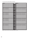
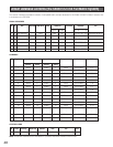
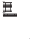
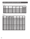
Default SYS.INI Contents