34
Coordinator Module Section 2-3
Note (1) The inrush current is given for a cold start at room temperature with an
AC power supply. The AC inrush control circuit uses a thermistor element
with a low-temperature current control characteristic. If the ambient tem-
perature is high or the FQM1 is hot-started, the thermistor will not be suf-
ficiently cool, and the inrush currents given in the table may be exceeded
by up to twice the given values. When selecting fuses or breakers for ex-
ternal circuits, allow sufficient margin in shut-off performance. If the
FQM1 is hot-started, the capacitor will not be discharged, and the inrush
currents given in the table may be exceeded by up to twice the given val-
ues.
(2) Disconnect the Power Supply Unit's LG terminal from the GR terminal
when testing insulation and dielectric strength. Testing the insulation and
dielectric strength with the LG terminal and the GR terminals connected
will damage internal circuits.
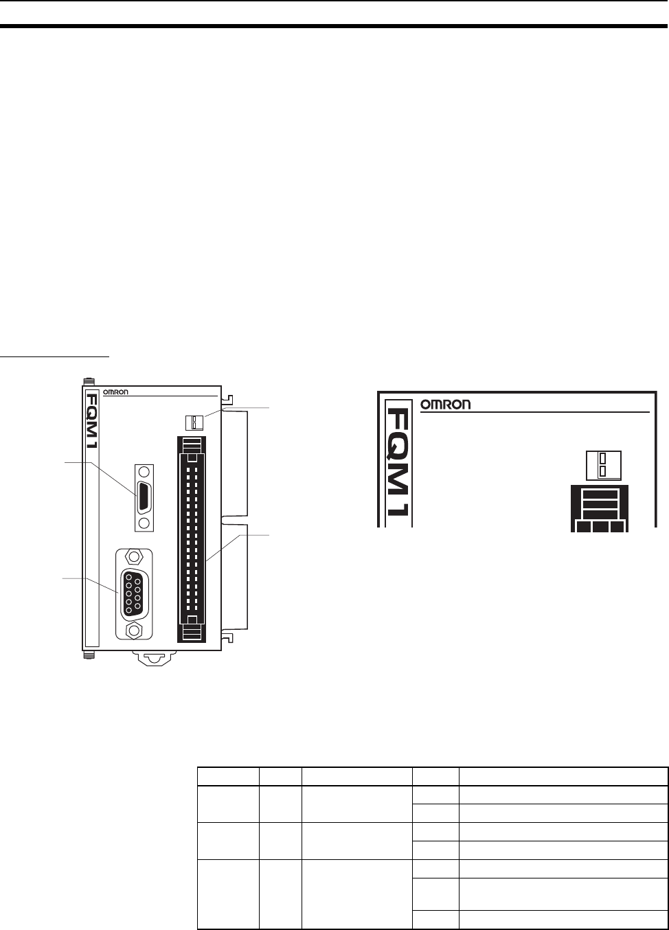
2-3 Coordinator Module
Nomenclature
Note Cover the peripheral port and RS-232C port with the supplied covers when
the ports are not being used to prevent dust contamination.
Indicators
FLEXIBLE
MOTION
CONTROLLER
RDY
RUN
ERR
PRPHL
COMM1
COMM2
PERIPHERAL
PORT
ON
OFF
CM001
2
CN1
RS422
1
4039
1 2
FLEXIBLE
MOTION
CONTROLLER
RDY
RUN
ERR
PRPHL
COMM1
COMM2
ON
OFF
CM001
1 2
Peripheral
port baud rate
detection/System
Setup switch
40-pin connector
㧔24 general-purpose
I/O points and RS-422A㧕
Peripheral
port
RS-232C
port
Coordinator Module
Indicators
Indicator Color Name Status Meaning
RDY Green Module operation Lit The Module is operating normally.
Not lit Module error (e.g., WDT error).
RUN Green Program execution Lit Executing internal Module program.
Not lit Internal Module program stopped.
ERR Red Module error Lit Fatal error.
Flash-
ing
Non-fatal error.
Not lit Module operating normally.


