132
Serial Communications Section 6-1
6-1-4 Serial PLC Links
Overview The FQM1 can be connected to a Serial PLC Link by linking to a Serial PLC
Master. (It cannot be connected by the Complete Link Method.) Program-free
data exchange can be achieved between the master and slave by connecting
a CJ1M CPU Unit as the master and the FQM1 as the slave. The FQM1 con-
nection is made to the RS-232C port on the Coordinator Module.
CIO 0080 to CIO 0099 in the Serial PLC Link Bit Area in the Coordinator Mod-
ule are shared with the CJ1M master as shown below.
CIO 0080 to CIO 0089: CJ1M master to FQM1 slave
CIO 0090 to CIO 0099: FQM1 slave to CJ1M maser
Note Use a CJ1W-CIF11 RS-232C to RS-422A/485 Conversion Adapter when con-
necting more than one FQM1 to the same CJ1M CPU Unit (1:N, where N = 8
max.).
Up to 10 words can be sent by the CJM1 and FQM1. Fewer words can be
sent by setting the number of link words, but the number of words will be the
same for both the CJM1 and FQM1.
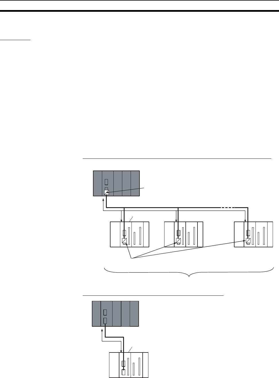
System Configuration 1:N Connection between CJ1M and FQM1 Controllers (8 Nodes Max.)
1:1 Connection between CJ1M and FQM1 Controller
RS-422A/485
CJ1W-CIF11 RS-232C to RS-422A/485
Conversion Adapter connected to RS-232C port
CJ1M CPU Unit (master)
Coordinator Module
Data sharing
FQM1
(slave)
8 nodes max.
CJ1W-CIF11 RS-232C to RS-422A/485
Conversion Adapters connected to RS-232C ports
FQM1
(slave)
FQM1
(slave)
RS-232C
CJ1M CPU Unit (master)
Coordinator Module
Data sharing
FQM1
(slave)


