201
Functions for Servo Drivers Compatible with Absolute Encoders Section 7-7
•Example 1
A value between 0 and 65,534 is set in the Servo Driver, the System
Setup’s Counter 1 Counter operation is set to an absolute linear (CW
−)
counter, and the Servo Driver’s reverse rotation mode setting
(Pn000.0) is set to 0 (+ command for rotation in CCW direction).
•Example 2
The System Setup’s Counter 1 Counter operation is set to an absolute
linear (CW
+) counter and the Servo Driver’s reverse rotation mode set-
ting (Pn000.0) is set to 1 (+ command for rotation in CW direction).
Note When using an absolute linear (CW
−) counter, the phase-B phase can be
inverted with an FQM1-series Servo Relay Unit so that the Servo Driver’s
operation matches the pulse output operation.
7-7-4 Counter Operation
Counting Operation The counting operations performed in the absolute linear (CW−), absolute lin-
ear (CW+), and absolute circular counters are the same as the pulse input
function’s linear and circular counters. However, the normal linear counter
does not have the function that receives the rotation data stored in a Servo
Driver compatible with an absolute encoder.
Counter Operation
Details
The details of the absolute linear (CW−), absolute linear (CW+), and absolute
circular counters are as follows:
Absolute Linear (CW
−)
Counter (CCW Rotation
for + Count)
When an absolute encoder rotates in reverse, the pulse information is
counted with a linear counter. Use this mode when the Servo Driver’s reverse
rotation mode parameter has been set to positive (+) command for CCW rota-
tion.
Absolute Linear (CW+)
Counter (CW Rotation for
+ Count)
When an absolute encoder rotates forward, the pulse information is counted
with a linear counter. Use this mode when the Servo Driver’s reverse rotation
mode parameter has been set to positive (+) command for CW rotation.
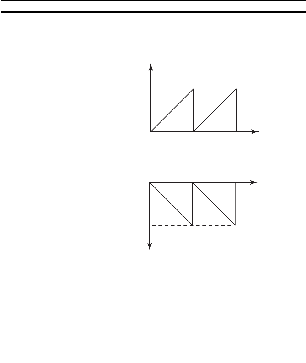
0
PV of +65,534
ABS PV is a positive value.
0
PV of −65,534
ABS PV is a negative value.


