


DMC-3425 Chapter 2 Getting Started• 27
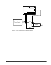
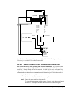
The DMC-3425 outputs STEPY signals on the ICM-1460 terminal labeled ERROR,
and outputs DIRX on the ICM-1460 terminal labeled AMPEN. X-axis connections
are identical to the DMC-3415.
Consult the documentation for your step motor amplifier for proper connections.
Step C. Configure DMC-3425 for motor type using MT command. You can configure the
DMC-3425 for active high or active low pulses. Use the command MT 2 for active
high step motor pulses and MT -2 for active low step motor pulses. See description
of the MT command in the Command Reference.
Note: The DMC-3425 must be ordered as a DMC-3425-Stepper to drive two axes of stepper motors.
Step 9. Tune the Servo System
The system compensation provides fast and accurate response by adjusting the filter parameters. The
following presentation suggests a simple and easy way for compensation. More advanced design
methods are available with software design tools from Galil, such as the Windows Servo Design Kit
(WSDK software).
If the torque limit was set as a safety precaution in the previous step, you may want to increase this
value. See Step B of the above section “Setting Torque Limit as a Safety Precaution”
The filter has three parameters: the damping, KD; the proportional gain, KP; and the integrator, KI.
The parameters should be selected in this order.
To start, set the integrator to zero with the instruction
KI 0 <CR> Integrator gain
and set the proportional gain to a low value, such as
KP 1 <CR> Proportional gain
KD 100 <CR> Derivative gain
For more damping, you can increase KD (maximum is 4095). Increase gradually and stop after the
motor vibrates. A vibration is noticed by audible sound or by interrogation. If you send the command
TE <CR> Tell error
a few times, and get varying responses, especially with reversing polarity, it indicates system vibration.
When this happens, simply reduce KD.
Next you need to increase the value of KP gradually (maximum allowed is 1023). You can monitor the
improvement in the response with the Tell Error instruction
KP 10 <CR> Proportion gain
TE <CR> Tell error
As the proportional gain is increased, the error decreases.
Again, the system may vibrate if the gain is too high. In this case, reduce KP. Typically, KP should
not be greater than KD/4.
Finally, to select KI, start with zero value and increase it gradually. The integrator eliminates the
position error, resulting in improved accuracy. Therefore, the response to the instruction
TE <CR>
becomes zero. As KI is increased, its effect is amplified and it may lead to vibrations. If this occurs,
simply reduce KI.
For a more detailed description of the operation of the PID filter and/or servo system theory, see
Chapter 10 Theory of Operation.