


DMC-3425 Appendices• 181
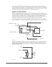
For example, if block 8 is configured as an output, the following command may be issued:
OP 7,,,,7
This command will set bits 1,2,3 (block 0) and bits 65,66,67 (block 8) to 1. Bits 4 through 8 and bits
68 through 80 will be set to 0. All other bits are unaffected.
When accessing I/O blocks configured as inputs, use the TIn command. The argument 'n' refers to the
block to be read (n=0,2,3,4,5,6,7,8 or 9). The value returned will be a decimal representation of the
corresponding bits.
Individual bits can be queried using the @IN[n] function (where n=1 through 8 or 17 through 80). If
the following command is issued;
MG @IN[17]
the controller will return the state of the least significant bit of block 2 (assuming block 2 is configured
as an input).
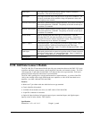
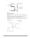
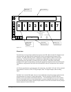
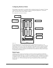
Connector Description:
The DMC-3425 controller with DB-14064 has two 50 Pin IDC header connectors. The connectors are
compatible with I/O mounting racks such as Grayhill 70GRCM32-HL and OPTO-22 G4PB24.
Note for interfacing to OPTO-22 G4PB24: When using the OPTO-22 G4PB24 I/O mounting rack,
the user will only have access to 48 of the 64 I/O points available on the controller. Block 5 and Block
9 must be configured as inputs and will be grounded by the I/O rack.
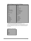
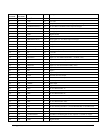
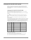
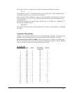
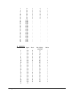
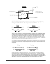
J6 50-PIN IDC
Pin Signal Block Bit @IN[n],
@OUT[n]
Bit No
1. I/O 4 40 7
3. I/O 4 39 6
5 I/O 4 38 5
7. I/O 4 37 4
9. I/O 4 36 3
11. I/O 4 35 2
13. I/O 4 34 1
15. I/O 4 33 0
17. I/O 3 32 7
19. I/O 3 31 6
21. I/O 3 30 5
23. I/O 3 29 4
25. I/O 3 28 3
27. I/O 3 27 2
29. I/O 3 26 1
31. I/O 3 25 0
33. I/O 2 24 7
35. I/O 2 23 6
37. I/O 2 22 5
39. I/O 2 21 4
41. I/O 2 20 3
43. I/O 2 19 2
45. I/O 2 18 1
47. I/O 2 17 0
49. +5V - - -