


DMC-3425 Chapter 1 Overview• 5
General I/O
The DMC-3415 provides interface circuitry for 7 TTL inputs and 3 TTL outputs. In addition, the
controller provides two 12-bit analog inputs. The general inputs can also be used for triggering a high-
speed positional latch for each axis.
NOTE: In order to accommodate 2 axes on the DMC-3425, many of the general I/O features become
dedicated I/O for the second axis. The standard DMC-3425 will have 3 TTL inputs, 3 TTL outputs and
2 analog inputs. If extra I/O is needed, the DB-14064 I/O daughter card increases general purpose I/O
by 64 points.
System Elements
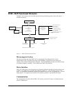
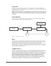
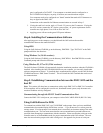
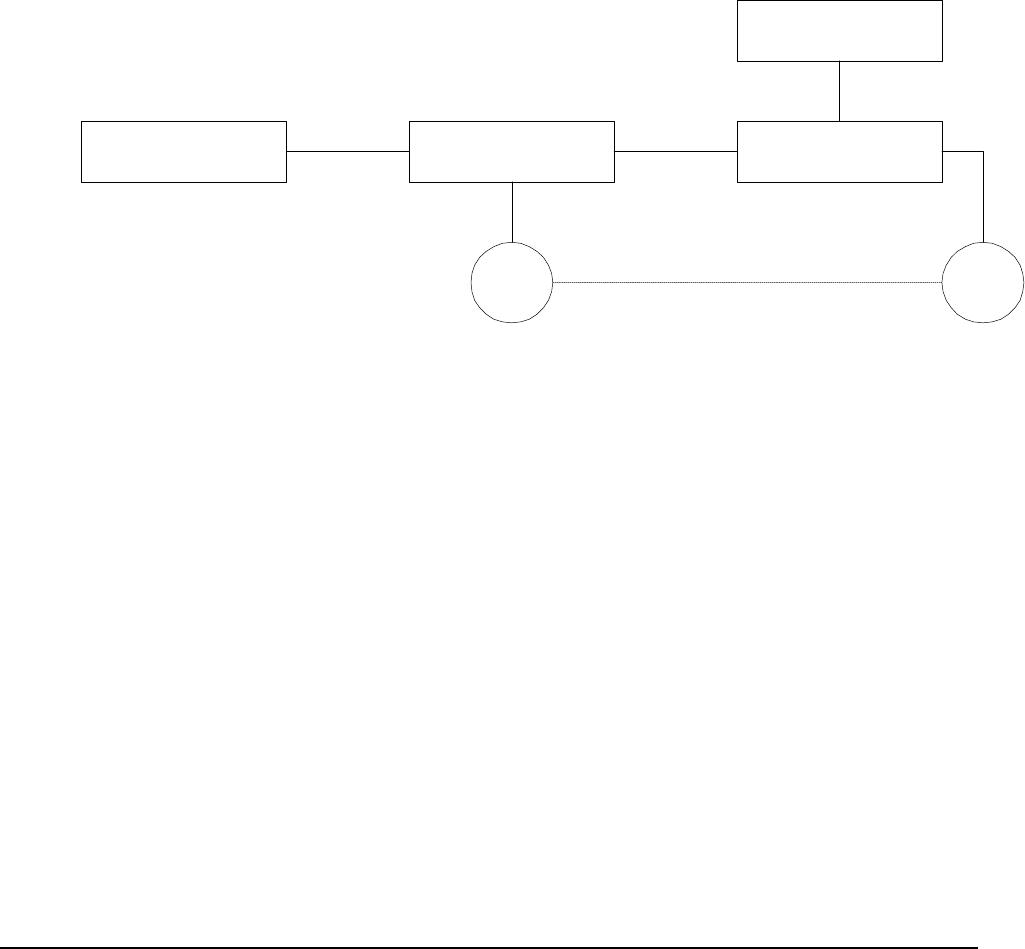
As shown in Fig. 1.2, the DMC-3425 is part of a motion control system, which includes amplifiers,
motors and encoders. These elements are described below.
Computer DMC-3425 Controller
A
mplifier (Driver)
Power Supply
Encoder Motor
Figure 1.2 - Elements of Servo systems
Motor
A motor converts current into torque, which produces motion. Each axis of motion requires a motor
sized properly to move the load at the required speed and acceleration. (Galil's "Motion Component
Selector" software can help you with motor sizing). Contact Galil for more information.
The motor may be a step or servo motor and can be brush-type or brushless, rotary or linear. For step
motors, the controller is capable of controlling full-step, half-step, or microstep drives. An encoder is
not required when step motors are used.
Amplifier (Driver)
For each axis, the power amplifier converts a +/-10 Volt signal from the controller into current to drive
the motor. For stepper motors, the amplifier converts step and direction signals into current. The
amplifier should be sized properly to meet the power requirements of the motor. For brushless motors,
an amplifier that provides electronic commutation is required or the controller must be configured to
provide sinusoidal commutation. The amplifiers may be either pulse-width-modulated (PWM) or
linear. They may also be configured for operation with or without a tachometer. For current
amplifiers, the amplifier gain should be set such that a 10 Volt command generates the maximum
required current. For example, if the peak motor current is 10A, the amplifier gain should be 1 A/V.
For velocity mode amplifiers, 10 Volts should run the motor at the maximum speed.