


DMC-3425 Chapter 2 Getting Started• 19
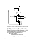
The DMC-3425 accepts single-ended or differential encoder feedback with or
without an index pulse. If you are not using the AMP-1460 or the ICM-1460, you
will need to consult the appendix for the encoder pinouts for connection to the
motion controller. The AMP-1460 and the ICM-1460 can accept encoder feedback
from a 10-pin ribbon cable or individual signal leads. For a 10-pin ribbon cable
encoder, connect the cable to the protected header connector labeled JP2. For
individual wires, simply match the leads from the encoder you are using to the
encoder feedback inputs on the interconnect board. The signal leads are labeled
CHA, CHB, and INDEX. These labels represent channel A, channel B, and the
INDEX pulse, respectively. For differential encoders, the complement signals are
labeled CHA-, CHB-, and INDEX-.
Note: When using pulse and direction encoders, the pulse signal is connected to
CHA and the direction signal is connected to CHB. The controller must be
configured for pulse and direction with the command CE. See the command
summary for further information on the command CE.
Step D. Verify proper encoder operation.
Once the encoder is connected as described above, turn the motor shaft and
interrogate the position with the instruction TP <return>. The controller response
will vary as the motor is turned.
At this point, if TP does not vary with encoder rotation, there are three possibilities:
1. The encoder connections are incorrect - check the wiring as necessary.
2. The encoder has failed - using an oscilloscope, observe the encoder signals.
Verify that both channels A and B have a peak magnitude between 5 and 12
volts. Note that if only one encoder channel fails, the position reporting varies
by one count only. If the encoder failed, replace the encoder. If you cannot
observe the encoder signals, try a different encoder.
3. There is a hardware failure in the controller - connect the same encoder to a
different axis. If the problem disappears, you probably have a hardware failure.
Consult the factory for help.
Step E. Connect Hall Sensors if available (sinusoidal commutation only)
Please consult factory before operating with sinusoidal commutation. Hall sensors
are only used with sinusoidal commutation on the DMC-3415 or DMC-3425 and are
not necessary for proper operation. The use of hall sensors allows the controller to
automatically estimate the commutation phase upon reset and also provides the
controller the ability to set a more precise commutation phase. Without hall sensors,
the commutation phase must be determined manually.
The Hall effect sensors are connected to the digital inputs of the controller. These
inputs can be used with the general-purpose inputs (bits 1 - 7). If you are using the
DMC-3425, only the first 3 inputs are available for general purpose.
Each set of inputs must use inputs that are in consecutive order. The input lines are
specified with the command, BI. For example, if the Hall sensors are connected to
inputs 1, 2 and 3, use the instruction:
BI1 <CR>
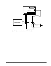
Step 8a. Connect Standard Servo Motor
The following discussion applies to connecting the DMC-3425 controller to standard servo motor
amplifiers: