


26 • Chapter 2 Getting Started DMC-3425
PRA=-1*(_BZA) <CR> Move A motor close to zero commutation phase
BGA <CR> Begin motion on A axis
AMA<CR> Wait for motion to complete on A axis
BZA=-1 <CR> Drive motor to commutation phase zero and leave motor
on
Method 3. Use the command, BC. This command uses the hall transitions to
determine the commutation phase. Ideally, the hall sensor transitions will be
separated by exactly 60° and any deviation from 60° will affect the accuracy of this
method. If the hall sensors are accurate, this method is recommended. The BC
command monitors the hall sensors during a move and monitors the Hall sensors for
a transition point. When that occurs, the controller computes the commutation phase
and sets it. For example, to initialize the motor upon power or reset, the following
commands may be given:
SH <CR> Enable motor
BC <CR> Enable the brushless calibration command
PR 50000 <CR> Command a relative position movement
BG <CR> Begin motion. When the hall sensors detect a phase
transition, the commutation phase is re-set.
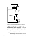
Step 8c. Connect Step Motors
In Stepper Motor operation, the pulse output signal has a 50% duty cycle. Step motors operate open
loop and do not require encoder feedback. When a stepper is used, the auxiliary encoder for the
corresponding axis is unavailable for an external connection. If an encoder is used for position
feedback, connect the encoder to the main encoder input corresponding to that axis. The commanded
position of the stepper can be interrogated with RP or DE. The encoder position can be interrogated
with TP. Only the DMC-3415 allows the use of the main encoder input with a stepper motor. The
DMC-3425 does not have this option.
The frequency of the step motor pulses can be smoothed with the filter parameter, KS. The KS
parameter has a range between 0.5 and 8, where 8 implies the largest amount of smoothing. See
Command Reference regarding KS.
The DMC-3425 profiler commands the step motor amplifier. All DMC-3425 motion commands apply
such as PR, PA, VP, CR and JG. The acceleration, deceleration, slew speed and smoothing are also
used. Since step motors run open-loop, the PID filter does not function and the position error is not
generated.
To connect step motors with the DMC-3425 you must follow this procedure:
Step A. Install SM jumper
Install the jumper SMX at location JP2 to enable stepper motor operation on the
DMC-3415. For the DMC-3425-Stepper, the jumpers should be loaded on SMX and
SMY. For a discussion of SM jumpers, see section “Step 2. Configuring Jumpers on
the DMC-3425”.
Step B. Connect step and direction signals from the controller to respective signals on your
step motor amplifier.
The DMC-3415 outputs STEPX (step) signals on the ICM-1460 terminal labeled
ACMD, and outputs DIRX (direction) signals on the ICM-1460 terminal labeled
ACMD2.