


DMC-3425 Appendices• 177
4
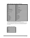
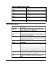
The screw terminals for ACMDX and ACMDY can provide access to 2 sets of signals, depending on
the placement of the 2 jumpers on JP3.
5
If the Opto-isolated input option is used, the output compare is NOT brought out to the ICM-1460. If
the output compare is to be used in conjunction with the opto-isolation, pin 23 of the Cable 37-Pin D
must be brought out externally. There are also options for using either terminal 1 or 2 as the Common
connection. Contact Galil for more information.
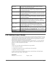
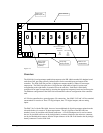
Opto-Isolation Option for ICM-1460
The ICM-1460 module from Galil has an option for opto-isolated inputs and outputs. This option is
specified as ICM-1460-OPTO*. With this option, the user is able to use voltages up to 24V on the
inputs and outputs of the controller.
The common point for the opto-isolation may be chosen from any of the following pins: pin 1 (labeled
as +12V), pin 2 (labeled as –12V) or pin 13 (labeled as CMP/ICOM). When pin 1 is used as
input/output common, the +12V output be comes inaccessible, when pin 2 is used, the –12V becomes
inaccessible, and when pin 13 is used, the output compare function is not available. This common
point must be specified at the time of ordering.
The ICM-1460 may also be configured such that the input/output common is jumpered to the internal
Vcc (+5V). By doing this, no screw connection is needed so no signals are lost.
A final option for the opto-isolation is for separate input/output commons. This allows the user to have
different voltage levels for the inputs and outputs. However, this requires the use of both pin 1 and pin
2 on the screw connection, making both +12V and –12V inaccessible on the screw terminals.
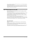
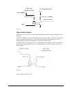
Opto-isolated inputs:
The signal "IN[x]" below is one of the isolated digital inputs where x stands for the digital input
terminals.
By connecting the OPTO-COMMON to the + side of an isolated power supply, the inputs will be
activated by sinking current. By connecting the OPTO-COMMON to the GND side of the power
supply, the inputs will be activated by sourcing current.
The opto-isolation circuit requires 1ma drive current with approximately 400 usec response time. The
voltage should not exceed 24V without placing additional resistance to limit the current to 11 mA.