


DMC-3425 Chapter 2 Getting Started• 9
Step 1. Determine Overall Motor Configuration
Before setting up the motion control system, the user must determine the desired motor configuration.
The DMC-3425 can control standard brush or brushless servo motors, sinusoidally commutated
brushless motors or stepper motors. For control of other types of actuators, such as hydraulics, please
contact Galil. The following configuration information is necessary to determine the proper motor
configuration:
Standard Servo Motor Operation:
The DMC-3425 has been setup by the factory for standard servo motor operation providing an analog
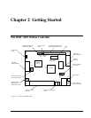
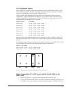
command signal of +/- 10 volt. The position of the jumpers at JP2/JP3 determines the type of output
the controllers will provide, analog motor command or PWM output. The installation of these jumpers
is discussed in the section “Configuring Jumpers on the DMC-3425”. Figure 2.2 shows how the
jumpers are configured for the standard output mode.
The DMC-3425 controller will output the analog command signal to either brush or brushless servo
amplifiers. Please note that if the brushless amplifier provides the sinusoidal commutation, the
standard servo motor operation from the controller will be used. If the commutation is to be performed
by the controller, please see below.
Sinusoidal Commutation:
Please consult the factory before operating with sinusoidal commutation.
Sinusoidal commutation is configured through a single software command, BA. This setting causes
the controller to reconfigure the control axis to output two commutated phases. The DMC-3425
requires two DAC outputs for a single axis of commutation. Issuing the BA command will enable the
second DAC for commutation.
If a DMC-3425 is used for sinusoidal commutation, the second axis will be used for the second DAC
phase. Please note that if the DMC-3425 is used for sinusoidal commutation, it will still be
represented by two axes within the distributed system, even though only one axis is truly active. The
DMC-3415 in brushless mode will take only a single axis within the distributed system.
Further instruction for sinusoidal commutation connections are discussed in Step 6.
Stepper Motor Operation:
The DMC-3415 can be configured to operate in stepper mode by installing a hardware jumper and
issuing a software command. The DMC-3425 can be configured to operate with two stepper motors by
ordering the DMC-3425-Stepper option from the factory. To configure the DMC-3425 for stepper
motor operation, the controller requires a jumper for the stepper motors and the command, MT, must
be given. The installation of the stepper motor jumper is discussed in the following section entitled
"Configuring Jumpers on the DMC-3425". Further instructions for stepper motor connections are
discussed in Step 8b.
Step 2. Configuring Jumpers on the DMC-3425
Master Reset and Upgrade Jumper
JP1 contains two jumpers, MRST and UPGD. The MRST jumper is the Master Reset jumper. When
MRST is connected, the controller will perform a master reset upon PC power up or upon the reset
input going low. Whenever the controller has a master reset, all programs, arrays, variables, and
motion control parameters stored in EEPROM will be ERASED.
The UPGD jumper enables the user to unconditionally update the controller’s firmware. This jumper
is not necessary for firmware updates when the controller is operating normally, but may be necessary
in cases of corrupted EEPROM. EEPROM corruption should never occur, however, it is possible if