


DMC-3425 Chapter 2 Getting Started• 23
ICM-1460
AMPEN
GND
ACMD
11 INHIBIT
4 +REF IN
2 SIGNALGND
Red Wire
Black Wire
Red Connector
Black Connector
Description Connection
Channel A+ MA+
Channel B+ MB+
Channel A- MA-
Channel B- MB-
Index - I-
Index + I+
Gnd GND
+5V 5V
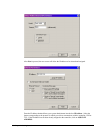
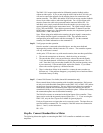
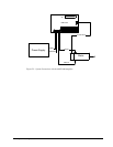
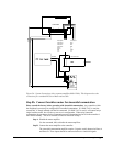
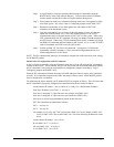
Figure 2.4 - System Connections with a separate amplifier (MSA 12-80). This diagram shows the
connections for a standard DC Servo Motor and encoder.
Step 8b. Connect brushless motor for sinusoidal commutation
Please consult the factory before operating with sinusoidal commutation. Any controller within
the distributed system may be configured for sinusoidal commutation. If a DMC-3415 is used, the
second DAC is simply initiated with the BA command. If a DMC-3425 is used, it will control only a
single brushless motor, but will take up two axes in configuration. When using sinusoidal
commutation, the parameters for the commutation must be determined and saved in the controller’s
non-volatile memory. The servo can then be tuned as described in Step 9.
Step A. Disable the motor amplifier
Use the command, MO, to disable the motor amplifiers.
Step B. Connect the motor amplifier to the controller.
The sinusoidal commutation amplifier requires 2 signals, usually denoted as Phase A
and Phase B. These inputs should be connected to the two sinusoidal signals