


DMC-3425 Appendices• 185
Configuring Hardware Banks
The extended I/O on the DMC-34x5 with DB-14064 is configured using the CO command. The banks
of buffers on the IOM-1964 are configured to match by inserting the appropriate IC’s and resistor
packs. The layout of each of the I/O banks is identical.
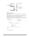
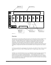
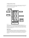
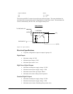
For example, here is the layout of bank 0:
Bank 0
IN
OUT
RP02 OUT
RP04 IN
RP03 OUT
U03 U04
U01 U02
D0
RP01
OUT
C6
17
18
19
20
21
22
23
24
Input Buffer IC's
Output Buffer IC's
Indicator LED's
Resistor Pack for
LED's
Resistor Pack for
outputs
Resistor Pack for
inputs
Resistor Pack for
outputs
Figure A-4
All of the banks have the same configuration pattern as diagrammed above in figure A-4. For
example, all banks have Ux1 and Ux2 output optical isolator IC sockets, labeled in bank 0 as U01 and
U02, in bank 1 as U11 and U12, and so on. Each bank is configured as inputs or outputs by inserting
optical isolator IC’s and resistor packs in the appropriate sockets. A group of eight LED’s indicates
the status of each I/O point. The numbers above the Bank 0 label indicate the number of the I/O point
corresponding to the LED above it.
Digital Inputs
Configuring a bank for inputs requires that the Ux3 and Ux4 sockets be populated with NEC2505
optical isolation integrated circuits. The IOM-1964 is shipped with a default configuration of banks 2-
7 configured as inputs. The output IC sockets Ux1 and Ux2 must be empty. The input IC’s are labeled
Ux3 and Ux4. For example, in bank 0 the IC’s are U03 and U04, bank 1 input IC’s are labeled U13
and U14, and so on. Also, the resistor pack RPx4 must be inserted into the bank to finish the input
configuration.