


8 • Chapter 2 Getting Started DMC-3425
Elements You Need
Before you start, you must get all the necessary system elements. These include:
1. (1) DMC-3425 or DMC-3415, (1) 37-pin cable (order Cable -37).
2. Servo motor(s) with encoders or stepper motors.
3. Appropriate motor drive - servo amp (Power Amplifier or AMP-1460) or stepper drive.
4. Power Supply for Amplifier
5. +5V, ±12V supply for DMC-3425
6. Communication CD from Galil
7. WSDK Servo Design Software (not necessary, but strongly recommended)
8. Interface Module ICM-1460 with screw-type terminals or integrated Interface
Module/Amplifier, AMP-1460. (Note: An interconnect module is not necessary, but strongly
recommended.) Also, the AMP-1460 only provides for 1 axis power amplification.
The motors may be servo (brush or brushless type) or steppers. The driver (amplifier) should be
suitable for the motor and may be linear or pulse-width-modulated and it may have current feedback or
voltage feedback.
For servo motors, the drivers should accept an analog signal in the +/-10 Volt range as a command.
The amplifier gain should be set so that a +10V command will generate the maximum required current.
For example, if the motor peak current is 10A, the amplifier gain should be 1 A/V. For velocity mode
amplifiers, a command signal of 10 Volts should run the motor at the maximum required speed.
For step motors, the driver should accept step and direction signals. For start-up of a step motor
system refer to Step 8c “Connecting Step Motors”.
The WSDK software is highly recommended for first time users of the DMC-3425. It provides step-
by-step instructions for system connection, tuning and analysis.
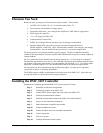
Installing the DMC-3425 Controller
Installation of a complete, operational DMC-3425 system consists of 9 steps.
Step 1. Determine overall motor configuration.
Step 2. Configuring jumpers on the DMC-3425.
Step 3. Connect the DC power supply and serial cable to the DMC-3425.
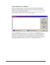
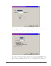
Step 4. Install the communications software.
Step 5. Establish communications between the DMC-3425 and the host PC.
Step 6. Set-up axis for sinusoidal commutation.
Step 7. Make connections to amplifier and encoder.
Step 8a. Connect standard servo motor.
Step 8b. Connect brushless motor for sinusoidal commutation.
Step 8c. Connect step motor.
Step 9. Tune servo system.
Step 10. Configure distributed control system.