


18 • Chapter 2 Getting Started DMC-3425
A signal breakout board of some type is strongly recommended. If you are using a breakout board
from a third party, consult the documentation for that board to insure proper system connection.
If you are using the ICM-1460 or AMP-1460 with the DMC-3425, connect the 37-pin cable between
the controller and interconnect module.
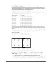
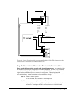
Here are the first steps for connecting a motion control system:
Step A. Connect the motor to the amplifier with no connection to the controller. Consult the
amplifier documentation for instructions regarding proper connections. Connect and
turn on the amplifier power supply. If the amplifiers are operating properly, the
motor should stand still even when the amplifiers are powered up.
Step B. Connect the amplifier enable signal. Before making any connections from the
amplifier to the controller, you need to verify that the ground level of the amplifier is
either floating or at the same potential as earth.
Note: If you are using a DMC-3425-Stepper, the amplifier enable signal is used for
the second stepper output.
WARNING: When the amplifier ground is not isolated from the power line or when it has a different potential
than that of the computer ground, serious damage may result to the computer controller and amplifier.
If you are not sure about the potential of the ground levels, connect the two ground
signals (amplifier ground and earth) by a 10 kΩ resistor and measure the voltage
across the resistor. Only if the voltage is zero, proceed to connect the two ground
signals directly.
The amplifier enable signal is used by the controller to disable the motor. This
signal is labeled AMPEN on the ICM-1460 and should be connected to the enable
signal on the amplifier. Note that many amplifiers designate this signal as the
INHIBIT signal. Use the command, MO, to disable the motor amplifiers - check to
insure that the motor amplifiers have been disabled (often this is indicated by an
LED on the amplifier).
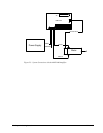
This signal changes under the following conditions: the watchdog timer activates,
the motor-off command, MO, is given, or the OE1 command (Enable Off-On-Error)
is given and the position error exceeds the error limit. As shown in Figure 3.1, AEN
can be used to disable the amplifier for these conditions.
The standard configuration of the AEN signal is TTL active high. In other words,
the AEN signal will be high when the controller expects the amplifier to be enabled.
The polarity and the amplitude can be changed if you are using the ICM-1460
interface board. To change the polarity from active high (5 volts = enable, zero volts
= disable) to active low (zero volts = enable, 5 volts = disable), replace the 7407 IC
with a 7406. Note that many amplifiers designate the enable input as ‘inhibit’.
To change the voltage level of the AEN signal, note the state of the JP1 jumper on
the ICM-1460. When the jumper is placed across 5V and AEN, the output voltage is
0-5V. To change to 12 volts, pull the jumper and rotate it so that +12V is connected
to AEN. If you remove the jumper, the output signal is an open collector, allowing
the user to connect an external supply with voltages up to 24V.
Step C. Connect the encoders
For stepper motor operation, an encoder is optional.
For servo motor operation, if you have a preferred definition of the forward and
reverse directions, make sure that the encoder wiring is consistent with that
definition.