


DMC-3425 Chapter 2 Getting Started• 21
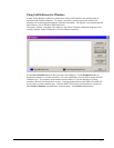
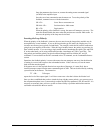
Once the parameters have been set, connect the analog motor command signal
(ACMD) to the amplifier input.
Issue the servo here command to turn the motors on. To test the polarity of the
feedback, command a move with the instruction:
SH <CR> Servo Here to turn motors on
PR 1000 <CR> Position relative 1000 counts
BG <CR> Begin motion
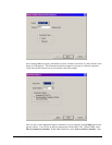
When the polarity of the feedback is wrong, the motor will attempt to run away. The
controller should disable the motor when the position error exceeds 2000 counts. In
this case, the polarity of the loop must be inverted.
Inverting the Loop Polarity
When the polarity of the feedback is incorrect, the user must invert the loop polarity and this may be
accomplished by several methods. If you are driving a brush-type DC motor, the simplest way is to
invert the two motor wires (typically red and black). For example, switch the M1 and M2 connections
going from your amplifier to the motor. When driving a brushless motor, the polarity reversal may be
done with the encoder. If you are using a single-ended encoder, interchange the signal CHA and CHB.
If, on the other hand, you are using a differential encoder, interchange only CHA+ and CHA-. The
loop polarity and encoder polarity can also be affected through software with the MT, and CE
commands. For more details on the MT command or the CE command, see the Command Reference
section.
Sometimes the feedback polarity is correct (the motor does not attempt to run away) but the direction
of motion is reversed with respect to the commanded motion. If this is the case, reverse the motor
leads AND the encoder signals.
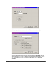
If the motor moves in the required direction but stops short of the target, it is most likely due to
insufficient torque output from the motor command signal ACMD. This can be alleviated by reducing
system friction on the motors. The instruction:
TT <CR> Tell torque
reports the level of the output signal. It will show a non-zero value that is below the friction level.
Once you have established that you have closed the loop with the correct polarity, you can move on to
the compensation phase (servo system tuning) to adjust the PID filter parameters, KP, KD and KI. It is
necessary to accurately tune your servo system to ensure fidelity of position and minimize motion
oscillation as described in the next section.