


142 • Chapter 7 Application Programming DMC-3425
Input Interrupt Function
The DMC-3425 provides an input interrupt function which causes the program to automatically
execute the instructions following the #ININT label. This function is enabled using the II m,n,o
command. The m specifies the beginning input and n specifies the final input in the range. The
parameter o is an interrupt mask. If m and n are unused, o contains a number with the mask. A 1
designates that input to be enabled for an interrupt, where 2
0
is bit 1, 2
1
is bit 2 and so on. For
example, II,,5 enables inputs 1 and 3 (2
0
+ 2
2
= 5). The RI command (not EN) is used to return from
the #ININT subroutine
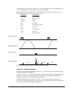
A low input on any of the specified inputs will cause automatic execution of the #ININT subroutine.
The Return from Interrupt (RI) command is used to return from this subroutine to the place in the
program where the interrupt had occurred. If it is desired to return to somewhere else in the program
after the execution of the #ININT subroutine, the Zero Stack (ZS) command is used followed by
unconditional jump statements.
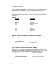
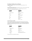
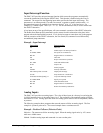
Example - Input Interrupt
Instruction Interpretation
#A Label #A
II 1 Enable input 1 for interrupt function
JG 30000,-20000 Set speeds on A and B axes
BG AB Begin motion on A and B axes
#B Label #B
TP AB Report A and B axes positions
WT 1000 Wait 1000 milliseconds
JP #B Jump to #B
EN End of program
#ININT Interrupt subroutine
MG "Interrupt has occurred" Displays the message
ST AB Stops motion on A and B axes
#LOOP;JP #LOOP,@IN[1]=0 Loop until Interrupt cleared
JG 15000,10000 Specify new speeds
WT 300 Wait 300 milliseconds
BG AB Begin motion on A and B axes
RI Return from Interrupt subroutine
Analog Inputs
The DMC-3425 provides two analog inputs. The value of these inputs in volts may be read using the
@AN[n] function where n is the analog input 1 or 2. The resolution of the standard Analog-to-Digital
conversion is 12 bits. Analog inputs are useful for reading special sensors such as temperature, tension
or pressure.
The following examples show programs that cause the motor to follow an analog signal. The first
example is a point-to-point move. The second example shows a continuous move.
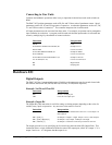
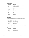
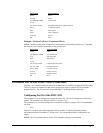
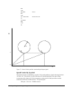
Example - Position Follower (Point-to-Point)
Objective - The motor must follow an analog signal. When the analog signal varies by 10V, motor
must move 10000 counts.
Method: Read the analog input and command A to move to that point.