


144 • Chapter 7 Application Programming DMC-3425
The least significant bit represents block 2 and the most significant bit represents block 9. The decimal
value can be calculated by the following formula. n = n
2
+ 2*n
3
+ 4*n
4
+ 8*n
5
+16* n
6
+32* n
7
+64*
n
8
+128* n
9
where n
x
represents the block. If the n
x
value is a one, then the block of 8 I/O points is to
be configured as an output. If the n
x
value is a zero, then the block of 8 I/O points will be configured
as an input. For example, if block 4 and 5 is to be configured as an output, CO 12 is issued.
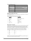
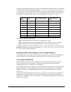
8-Bit I/O
Block
Block Binary Representation Decimal Value for
Block
17-24
2
2
0
1
25-32 3
2
1
1
2
33-40 4 2
2
4
41-48 5 2
3
8
49-56 6 2
4
16
57-64 7 2
5
32
65-72 8 2
6
64
73-80 9 2
7
128
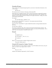
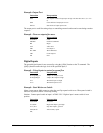
The simplest method for determining n:
Step 1. Determine which 8-bit I/O blocks to be configured as outputs.
Step 2. From the table, determine the decimal value for each I/O block to be set as an output.
Step 3. Add up all of the values determined in step 2. This is the value to be used for n.
For example, if blocks 2 and 3 are to be outputs, then n is 3 and the command, CO3, should be issued.
NOTE: This calculation is identical to the formula: n = n
2
+ 2*n
3
+ 4*n
4
+ 8*n
5
+16* n
6
+32* n
7
+64*
n
8
+128* n
9
where n
x
represents the block.
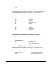
Saving the State of the Outputs in Non-Volatile Memory
The configuration of the extended I/O and the state of the outputs can be stored in the EEPROM with
the BN command. If no value has been set, the default of CO 0 is used (all blocks are inputs).
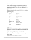
Accessing Extended I/O
When configured as an output, each I/O point may be defined with the SBn and CBn commands
(where n=1 through 8 and 17 through 80). Outputs may also be defined with the conditional
command, OBn (where n=1 through 8 and 17 through 80).
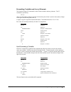
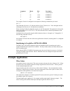
The command, OP, may also be used to set output bits, specified as blocks of data. The OP command
accepts 5 parameters. The first parameter sets the values of the main output port of the controller
(Outputs 1-8, block 0). The additional parameters set the value of the extended I/O as outlined:
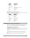
OP m,a,b,c,d
where m is the decimal representation of the bits 1-8 (values from 0 to 255) and a,b,c,d represent the
extended I/O in consecutive groups of 16 bits. (values from 0 to 65535). Arguments given for I/O
points that are configured as inputs will be ignored. The following table describes the arguments used
to set the state of outputs.