


146 • Chapter 7 Application Programming DMC-3425
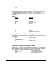
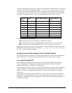
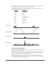
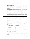
The program starts at a state that we define as #A. Here the controller waits for the input pulse on I1.
As soon as the pulse is given, the controller starts the forward motion.
Upon completion of the forward move, the controller outputs a pulse for 20 ms and then waits an
additional 80 ms before returning to #A for a new cycle.
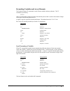
Instruction
Inter
p
retation
#A Label
AI1 Wait for input 1
PR 6370 Distance
SP 3185 Speed
BGA Start Motion
AMA After motion is complete
SB1 Set output bit 1
WT 20 Wait 20 ms
CB1 Clear output bit 1
WT 80 Wait 80 ms
JP #A Repeat the process
START PULSE I1
MOTOR VELOCITY
OUTPUT PULSE
TIME INTERVALS
move
output
wait ready move
Figure 7.1 - Motor Velocity and the Associated Input/Output signals
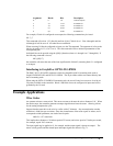
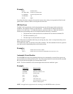
A-B (X-Y) Table Controller
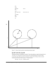
An A-B-C system must cut the pattern shown in Fig. 7.2. The A-B table moves the plate while the C-
axis raises and lowers the cutting tool.
The solid curves in Fig. 7.2 indicate sections where cutting takes place. Those must be performed at a
feedrate of 1 inch per second. The dashed line corresponds to non-cutting moves and should be
performed at 5 inch per second. The acceleration rate is 0.1 g.
The motion starts at point A, with the C-axis raised. An A-B motion to point B is followed by
lowering the C-axis and performing a cut along the circle. Once the circular motion is completed, the
C-axis is raised and the motion continues to point C, etc.