


DMC-3425 Chapter 10 Theory of Operation• 161
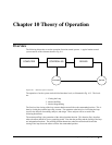
Motor-Amplifier
The motor amplifier may be configured in three modes:
1. Voltage Drive
2. Current Drive
3. Velocity Loop
The operation and modeling in the three modes is as follows:
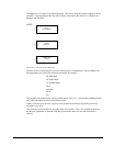
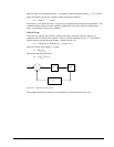
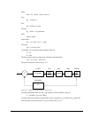
Voltage Drive
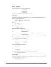
The amplifier is a voltage source with a gain of Kv [V/V]. The transfer function relating the input
voltage, V, to the motor position, P, is
(
)
(
)
[]
PV K KSST ST
Vt m e
=++11
where
TRJK
m
t
=
2
[s]
and
T
L
R
e
= [s]
and the motor parameters and units are
K
t
Torque constant [Nm/A]
R
Armature Resistance Ω
J
Combined inertia of motor and load [kg.m
2
]
L Armature Inductance [H]
When the motor parameters are given in English units, it is necessary to convert the quantities to MKS
units. For example, consider a motor with the parameters:
K
t
= 14.16 oz - in/A = 0.1 Nm/A
R = 2 Ω
J = 0.0283 oz-in-s
2
= 2.10
-4
kg . m
2
L = 0.004H
Then the corresponding time constants are
T
m
= 0.04 sec
and
T
e
= 0.002 sec
Assuming that the amplifier gain is Kv = 4, the resulting transfer function is
P/V = 40/[s(0.04s+1)(0.002s+1)]
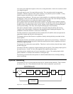
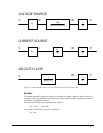
Current Drive
The current drive generates a current I, which is proportional to the input voltage, V, with a gain of Ka.
The resulting transfer function in this case is
P/V = K
a
K
t
/ Js
2