70
Reference Manual
00809-0100-4860, Rev BC
Section 5: Troubleshooting
January 2013
Troubleshooting
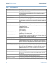
Table 5-1. Diagnostic Messages
Message Description
ROM CHECKSUM ERROR The EPROM memory checksum test has failed. The transmitter will remain in ALARM
until the ROM checksum test passes.
NV MEM CHECKSUM ERROR The User Configuration area in Nonvolatile EEPROM memory has failed the checksum
test. It is possible to repair this checksum by verifying and reconfiguring ALL
transmitter parameters. The transmitter will remain in ALARM until the EEPROM
checksum test passes.
RAM TEST ERROR Transmitter RAM memory test has detected a failed RAM location. The transmitter
will remain in ALARM until the RAM test passes.
DIGITAL FILTER ERROR The digital filter in the transmitter electronics is not reporting. The transmitter will
remain in ALARM until the digital signal processor resumes reporting flow data.
COPROCESSOR ERROR If this occurs at power-up, the RAM/ROM test in the coprocessor has failed. If this
occurs during normal operations, the coprocessor has reported either a math error
or a negative flow. This is a FATAL error and the transmitter will remain in ALARM until
reset.
SOFTWARE DETECTED ERROR The software has detected corrupted memory. One or more of the software tasks
has corrupted memory. This is a FATAL error and the transmitter will remain in ALARM
until reset.
ELECTRONICS FAILURE This is a summary error indication. This error will be reported if any of the following
error conditions are present:
1. ROM Checksum Error
2. NV Memory Checksum Error
3. RAM Test Error
4. ASIC Interrupt Error
5. Digital FIlter Error
6. Coprocessor Error
7. Software Detected Error
TRIGGER LEVEL OVERRANGE The trigger level in the transmitter digital signal processing has been set beyond its
limit. Use manual filter adjustment to “Increase Filtering” or “Increase Sensitivity” to
bring the trigger level back within range.
LOW PASS FILT OVERRANGE The low pass filter in the transmitter digital signal processing has been set beyond its
limit. Use manual filter adjustment to “Increase Filtering” or “Increase Sensitivity” to
bring the low pass filter adjustment back within range.
ELECTRONICS TEMP OUT OF LIMITS The electronics temperature sensor within the transmitter is reporting a value out of
range.
INVALID CONFIGURATION Certain configuration parameters are out of range. Either they have not been
properly configured, or they have been forced out of range as a result of a change to a
related parameter. For example: When using mass flow units, changing the process
density to a value too low could push the configured Upper Range Value beyond the
sensor limit. In this case, the Upper Range Value would need to be reconfigured.
FACTORY EEPROM
CONFIG ERROR
The factory configured values in non-volatile EEPROM memory have become
corrupted. This is a FATAL error. The transmitter will remain in ALARM until reset.
LOW FLOW CUTOFF OVERRANGE On start-up, the configured setting for the VDSP Low Flow Cutoff setting was found
to be too high or too low. The increase range or decrease no flow noise command of
the VDSP Low Flow Cutoff setting has not yet brought the setting into a valid range.
Continue adjusting the Low Flow Cutoff to a valid value or use the Filter Restore
Option.
T/C A/D ERROR The ASIC responsible for the analog to digital conversion of the process temperature
thermocouple and cold junction RTD has failed. If the problem persists, replace the
transmitter electronics.
THERMOCOUPLE OPEN The thermocouple that is used to measure the process temperature has failed. Check
the connections to the transmitter electronics. If the problem persists, replace the
thermocouple.
CJ RTD FAILURE The RTD temperature sensing device for sensing the cold junction temperature has
failed. If the problem persists, replace the transmitter electronics.
FLOW SIMULATION The transmitter flow signal is being simulated by a signal generator internal to the
transmitter. The actual flow through the meter body is NOT being measured.
SENSOR SIGNAL IGNORED The transmitter flow signal is being simulated by a signal generator external to the
transmitter. The actual flow through the meter body is NOT being measured.


