


26
Reference Manual
00809-0100-4860, Rev BC
Section 2: Installation
January 2013
Installation
Note
The circuit board is electrostatically sensitive. Be sure to observe handling precautions for
static-sensitive components.
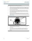
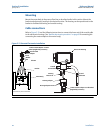
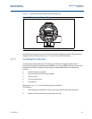
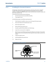
3. Insert the mounting screws into the LCD indicator.
4. Remove the two jumpers on the circuit board that coincide with the Alarm and the
Security settings.
5. Insert the connector into the Alarm / Security junction.
6. Gently slide the LCD indicator onto the connector and tighten
the screws into place.
7. Insert jumpers into ALARM and SECURITY positions on the face of the LCD indicator.
8. Attach the extended cover and tighten at least one-third turn past o-ring contact.
Note
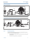
The indicator may be installed in 90-degree increments for easy viewing. Mounting screws may
need to be installed in the alternative holes based on LCD orientation. One of the four
connectors on the back of the indicator assembly must be positioned to fit into the ten-pin
connector on the electronic board stack.
Note the following LCD temperature limits:
2.8 Transient protection
The optional transient terminal block prevents damage to the flowmeter from transients
induced by lightning, welding, heavy electrical equipment, or switch gears. The transient
protection electronics are located in the terminal block.
The transient terminal block meets the following specifications:
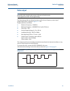
IEEE C62.41 - 2002 Category B.
3 kA crest (8 X 20
s)
6 kV crest (1.2 X 50
s)
6 kV/0.5 kA (0.5
s, 100 kHz, ring wave)
Note
The ground screw inside the terminal housing must be tightened for the proper operation of the
transient protection. Also, a high-current ground connection to earth is required.
Operating: –4 to 185 °F (–20 to 85 °C)
Storage: –50 to 185 °F (–46 to 85 °C)