13
Reference Manual
00809-0100-4860, Rev BC
Section 2: Installation
January 2013
Installation
2.5.5 Flanged-style flowmeter mounting
Physical mounting of a flanged-style flowmeter is similar to installing a typical section of pipe.
Conventional tools, equipment, and accessories (such as bolts and gaskets) are required.
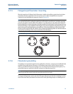
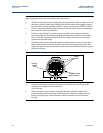
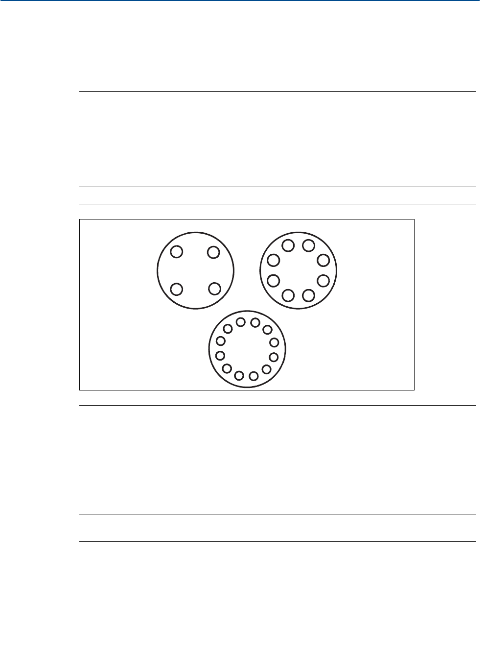
Tighten the nuts following the sequence shown in Figure 2-8.
Note
The required bolt load for sealing the gasket joint is affected by several factors, including operating
pressure and gasket material, width, and condition. A number of factors also affect the actual bolt
load resulting from a measured torque, including condition of bolt threads, friction between the nut
head and the flange, and parallelism of the flanges. Due to these application-dependent factors, the
required torque for each application may be different. Follow the guidelines outlined in the ASME
Pressure Vessel Code (Section VIII, Division 2) for proper bolt tightening. Make sure the flowmeter is
centered between flanges of the same nominal size as the flowmeter.
2.5.6 Flowmeter grounding
Grounding is not required in typical vortex applications; however, a proper ground will eliminate
possible noise pickup by the electronics. Grounding straps may be used to ensure that the
meter is grounded to the process piping. If you are using the transient protection option (T1),
grounding straps are required to provide a proper low impedance ground.
Note
Properly ground flow meter body and transmitter per the local code.
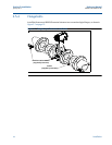
To use grounding straps, secure one end of the grounding strap to the bolt extending from the
side of the meter body and attach the other end of each grounding strap to a suitable ground.
Figure 2-8. Flange Bolt Torquing Sequence
1
3
4
2
1
1
2
2
3
3
4
4
5
5
6
6
7
7
8
8
9
10
11
12


