


7
Reference Manual
00809-0100-4860, Rev BC
Section 2: Installation
January 2013
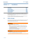
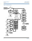
Installation
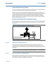
Upstream/Downstream piping
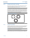
The vortex meter may be installed with a minimum of ten diameters (D) of straight pipe length
upstream and five diameters (D) of straight pipe length downstream.
Rated accuracy is based on the number of pipe diameter from an upstream disturbance. No
K-factor correction is required if the meter is installed with 35 D upstream and 5 D downstream.
The value of the K-factor may shift up to 0.5% when the upstream straight pipe length is
between 10D and 35D. Please see Technical Data Sheet (00816-0100-3250) on Installation
Effects for optional K-factor corrections. This effect can be corrected for using the Installation
Effect Correction Factor (See page 52).
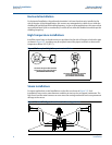
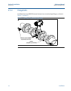
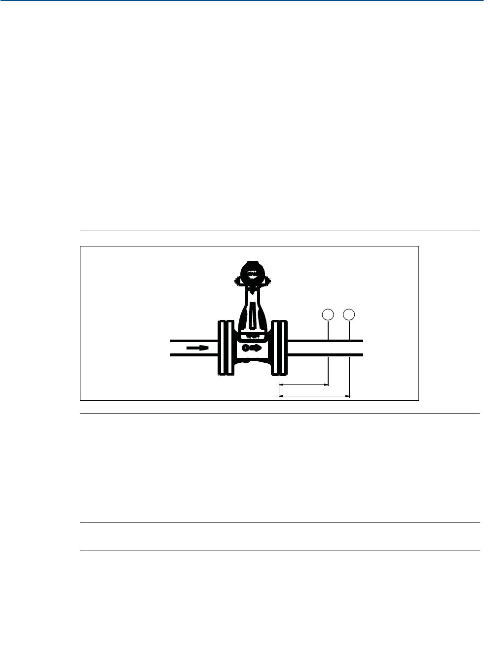
Pressure and temperature transmitter location
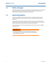
When using pressure and temperature transmitters in conjunction with the Rosemount 8600D
for compensated mass flows, install the transmitter(s) downstream of the Vortex Flowmeter.
See Figure 2-4.
2.2.4 Wetted material selection
Ensure that the process fluid is compatible with the meter body wetted materials when
specifying the Rosemount 8600D. Corrosion will shorten the life of the meter body. Consult
recognized sources of corrosion data or contact your Rosemount Sales Representative for more
information.
Note
For accurate results perform a Positive Material Identification (PMI) test on a machined surface.
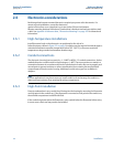
2.2.5 Environmental considerations
Avoid excessive heat and vibration to ensure maximum flowmeter life. Typical problem areas
include high-vibration lines with integrally mounted electronics, warm-climate installations in
direct sunlight, and outdoor installations in cold climates.
Figure 2-4. Pressure and Temperature Transmitter Location
NOTE: The MTA option can be purchased for an integral
temperature measurement and mass flow temperature
compensation for saturated steam only.
4 Downstream
6 Downstream
TP