25
Reference Manual
00809-0100-4860, Rev BC
Section 2: Installation
January 2013
Installation
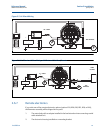
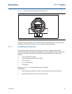
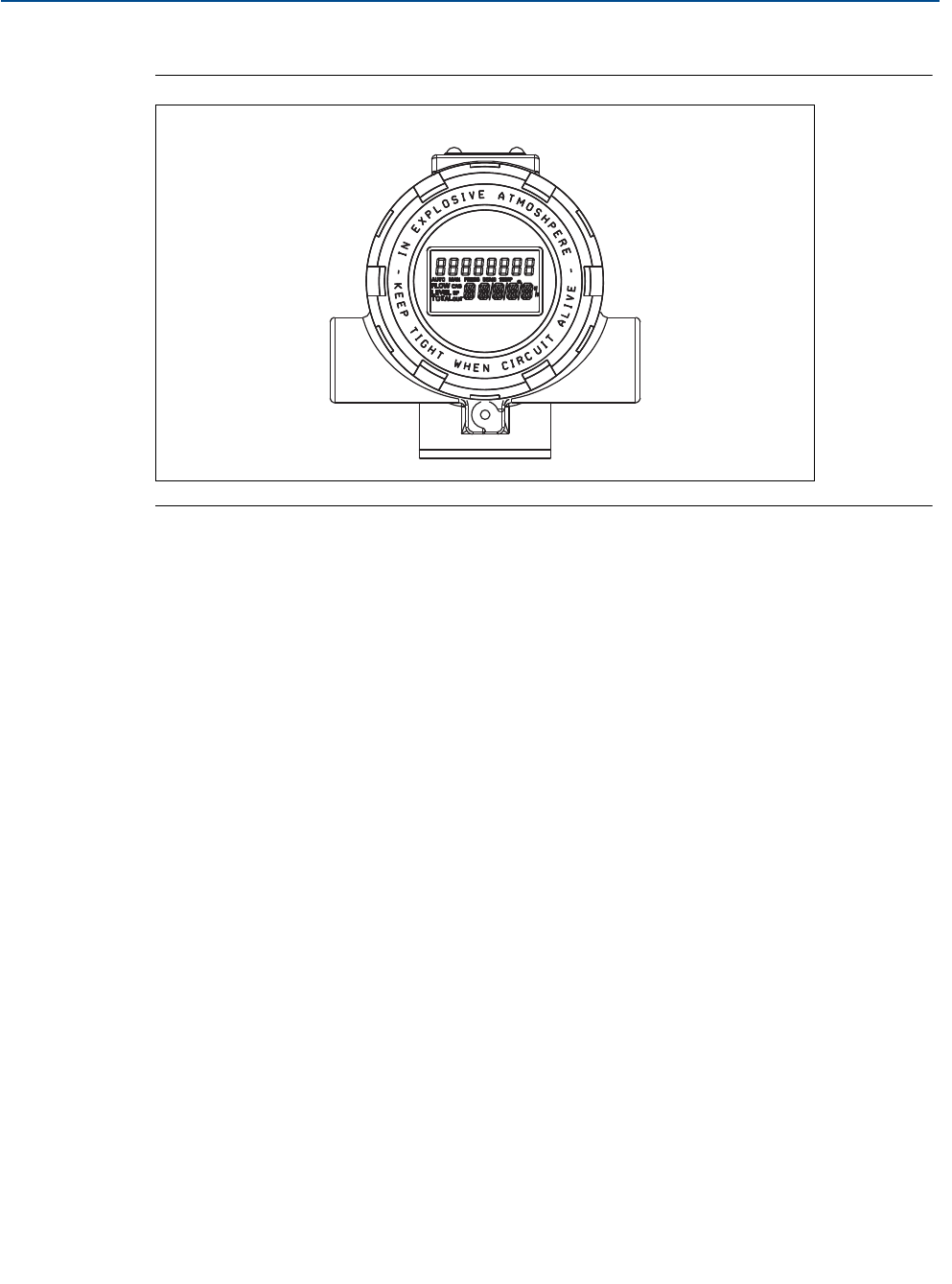
Figure 2-17 shows the indicator display with all segments lit.
A HART-based communicator can be used to change the engineering units of the parameters
displayed on the indicator. (SeeSection 4: Operation for more information).
2.7.1 Installing the indicator
For flowmeters ordered with the LCD indicator, the indicator is shipped installed. When
purchased separately from the Rosemount 8600D, you must install the indicator using a small
instrument screwdriver and the indicator kit (part number 8600-5640). The indicator kit
includes:
One LCD indicator assembly
One extended cover with o-ring installed
One connector
Two mounting screws
Two jumpers
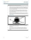
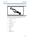
Referring to Figure 2-16, use the following steps to install the
LCD indicator:
1. If the flowmeter is installed in a loop, secure the loop and disconnect the power.
2. Remove the flowmeter cover on the electronics side.
Figure 2-17. Optional Liquid Crystal Display


