


19
Reference Manual
00809-0100-4860, Rev BC
Section 2: Installation
January 2013
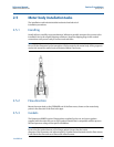
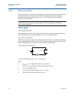
Installation
Pulse output
Note
Remember when using the pulse output, all power to the electronics
is still supplied over the 4–20 mA signal wiring.
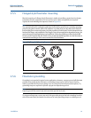
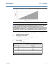
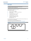
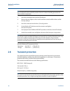
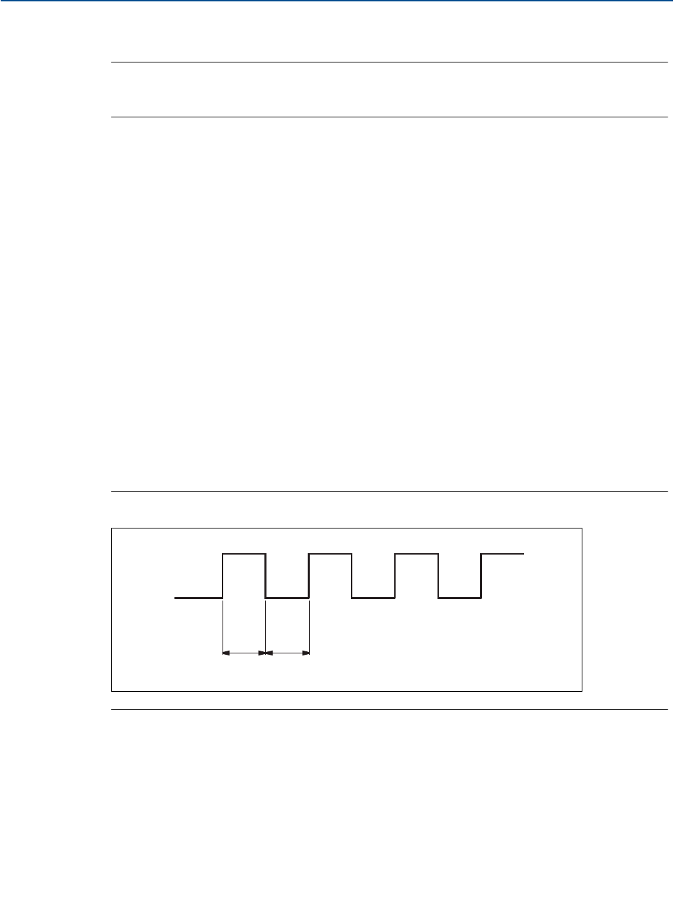
The flowmeter provides an isolated transistor switch-closure frequency output signal
proportional to flow, as shown in Figure 2-11. The
frequency limits are as follows:
Maximum Frequency = 10000 Hz
Minimum Frequency = 0.0000035 Hz (1 pulse/79 hours)
Duty Cycle = 50%
External Supply Voltage (V
s
): 5 to 30 Vdc
Load Resistance (R
L
): 100 to 100 k
Max Switching Current = 75 mA >= V
S
/R
L
Switch Closure: Transistor, open collector
Open contact < 50
A leakage
Close contact < 20
The output may drive an externally powered electromechanical or electronic totalizer, or may
serve as a direct input to a control element.
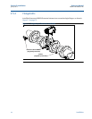
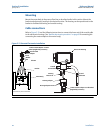
To connect the wires, remove the FIELD TERMINALS side cover
of the electronics housing. Connect the wires as shown in Figure 2-14 on page 21.
Figure 2-11. Example: The pulse output will maintain a 50 percent duty cycle for all
frequencies.
50% Duty Cycle