


23
Reference Manual
00809-0100-4860, Rev BC
Section 2: Installation
January 2013
Installation
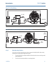
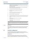
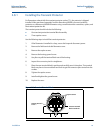
1. If you plan to run the coaxial cable in conduit, carefully cut the conduit to the desired
length to provide for proper assembly
at the housing. A junction box may be placed in the conduit run to provide a space for
extra coaxial cable length.
2. Slide the conduit adapter or cable gland over the loose end of the coaxial cable and
fasten it to the adapter on the meter body bracket.
3. If using conduit, route the coaxial cable through the conduit.
4. Place a conduit adapter or cable gland over the end of the
coaxial cable.
5. Remove the housing adapter from the electronics housing.
6. Slide the housing adapter over the coaxial cable.
7. Remove one of the four housing base screws.
8. Attach the coaxial cable ground wire to the housing via the housing base ground screw.
9. Attach and securely tighten the coaxial cable nut to the connection on the electronics
housing.
10. Align the housing adapter with the housing and attach
with two screws.
11. Tighten the conduit adapter or cable gland to the
housing adapter.
Caution
To prevent moisture from entering the coaxial cable connections, install the interconnecting
coaxial cable in a single dedicated conduit run or use sealed cable glands at both ends of the
cable.
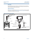
2.6.8 Calibration
Rosemount 8600D Flowmeters are wet-calibrated at the factory and need no further calibration
during installation. The calibration factor (K-factor) is indicated on each meter body and is
entered into the electronics. Verification can be accomplished with a Field Communicator
or AMS.
2.7 Software configuration
To complete the installation of the Rosemount 8600D Vortex Flowmeter, configure the
software to meet the requirements of your application. If the flowmeter was pre-configured at
the factory, it may be ready to install. If not, refer to Section 3: Configuration.
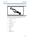
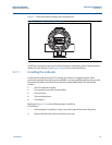
LCD indicator
The LCD indicator (option M5) provides local indication of the output and abbreviated
diagnostic messages governing operation of the flowmeter. The indicator is located on the
electronics side of the flowmeter electronics. An extended cover is required to accommodate