24
Reference Manual
00809-0100-4860, Rev BC
Section 2: Installation
January 2013
Installation
the indicator. Figure 2-16 shows the flowmeter fitted with the LCD indicator and extended
cover.
The indicator features an eight-character (and five alphanumeric) liquid crystal display that
gives a direct reading of the digital signal from the microprocessor. During normal operation,
the display can be configured to alternate between the following readings:
1. Primary variable in engineering units
2. Percent of range
3. Totalized flow
4. 4–20 mA electrical current output
5. Shedding Frequency
6. Electronics Temperature
7. Pulse Output Frequency
8. Process Temperature
(MTA Option Only)
9. Mass Flow
10. Volume Flow
11. Velocity Flow
12. Calculated Process Density
(MTA Option Only)
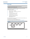
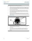
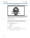
Figure 2-16. Rosemount 8600D with Optional Indicator
Electronics Board


