14
Reference Manual
00809-0100-4860, Rev BC
Section 2: Installation
January 2013
Installation
2.6 Electronics considerations
Both integral and remote mounted electronics require input power at the electronics. For
remote mount installations, mount the electronics
against a flat surface or on a pipe that is up to two inches (50 mm) in diameter.
Remote mounting hardware includes an L bracket that is stainless steel and one stainless steel
u-bolt. See Appendix A: Reference data, “Dimensional drawings” on page 107 for dimensional
information.
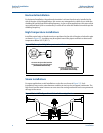
2.6.1 High-Temperature installations
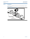
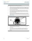
Install the meter body so the electronics are positioned to the side of or
below the pipe as shown in Figure 2-2 on page 6. Insulation may be required around the pipe to
maintain an ambient transmitter temperature below 185 °F (85 °C) or the more restrictive
temperature ratings marked on hazardous locations tags.
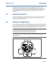
2.6.2 Conduit connections
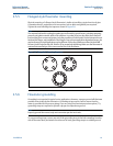
The electronics housing has two ports for
1
/2–14 NPT or M20ϫ1.5 conduit connections. Unless
marked otherwise conduit entries in the housing are
1
/2 NPT. These connections are made in a
conventional manner in accordance with local or plant electrical codes. Be sure to properly seal
unused ports to prevent moisture or other contamination from entering the terminal block
compartment of the electronics housing. Additional conduit entry types are available via
adapters.
Note
In some applications it may be necessary to install conduit seals and arrange for conduits to
drain to prevent moisture from entering the wiring compartment.
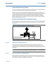
2.6.3 High-Point installation
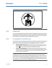
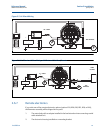
Prevent condensation in any conduit from flowing into the housing by mounting the flowmeter
at a high point in the conduit run. If the flowmeter is mounted at a low point in the conduit run,
the terminal compartment could fill with fluid.
If the conduit originates above the flowmeter, route conduit below the flowmeter before entry.
In some cases a drain seal may need to be installed.


