


VISTA-10SE Installation and Setup Guide
8–2
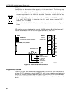
Sounder Connections and Power
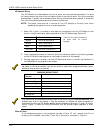
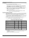
The VISTA-10SE provides a 12VDC output, which can power external alarm sounders, bells,
or sirens (see table of compatible sounders on a previous page). This output activates a
sounder when an alarm occurs.
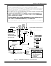
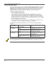
Make connections to alarm output terminals 3 (+) and 4 (–). See Figure 12 below.
U
L
The total current drawn from the alarm output and the
auxiliary power output, combined, cannot
exceed 600mA. In addition, the sounding device must be a UL Listed audible signal appliance
rated to operate in a 10.2-13.8VDC range. Example: Wheelock Signals Inc. siren model 34T-12
(provides 85dBA for NFPA 74 and Standard 985).
Non-UL Installations
The total current drawn from this output cannot exceed 2 amps. A battery must be installed
because the battery supplies this current.
Going beyond the limits indicated (2 amps) will overload the power supply, and cause the
electronic circuit protecting the sounder output to trip.
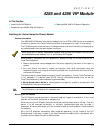
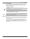
Sounder Supervision
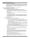
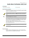
The VISTA-10SE contains a sounder (Bell) supervision option. To activate the Bell
supervision option:
1. Cut the red Bell Supervision Jumper located above terminals 2 and 3 on the control board.
See Figure 13 below.
2. Connect a 1k ohm resistor across the terminals of the last sounding device, not across the
control's terminals.
+
+
3
4
NO. 702
SIREN
CONTROL
BOARD
ALARM
OUTPUT
V10SE-018-V0
Figure 12. Typical Sounder Wiring
+
+
3
4
OBSERVE
POLARITY
TERMINALS ON
CONTROL BOARD
ALARM
OUTPUT
TERMINALS
CUT RED JUMPER ON
CONTROL BOARD
TO ENABLE BELL
(SOUNDER) SUPERVISION
IF BELL SUPERVISION IS ENABLED (RED JUMPER
ON CONTROL BOARD IS CUT), CONNECT A 1000
OHM RESISTOR ACROSS THE EXTERNAL
SOUNDER, AS SHOWN BY THE DASHED LINE.
DO NOT CONNECT THE RESISTOR AT THE
ALARM OUTPUT TERMINALS THEMSELVES!
EXTERNAL
ALARM
SOUNDER
1000
OHM
EOL
RESISTOR
V10SE-031-V0
Figure 13. Bell Supervision Wiring
Testing the Sounder
After you install the sounder, test the security system carefully, as follows:
1. Connect the battery wires from the control board to the battery, observing correct polarity.
2. Enter the Installer code (4111) and press the TEST (5) key on the keypad.
The external sounder should sound for 1 second if the sounder is working and proper
connections have been made. Note that if the backup battery is discharged, the sounder
does not turn on.
3. To turn off the Test mode, enter the Installer code (4111) and press the OFF key.
4. Disconnect the battery wires from the battery terminals.
5. Unplug the AC transformer from the AC outlet.