


VISTA-10SE Installation and Setup Guide
5-6
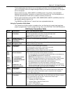
5800 Series Transmitters Table (
continued)
Model Description Input Type and Special Notes
5817
(cont'd.)
Multi-Point Universal
Transmitter
(cont'd.)
DIP Switches:
Set all DIP switches to the OFF position when enrolling the
serial number.
NOTE:
All loops must be assigned the same input type.
5818 Recessed Magnetic
Contact Transmitter
Enroll as “3” for RF (supervised).
5819
5819
BRS
5819
WHS
Shock Processor
Transmitter
Enroll as “3” for RF (supervised).
Has three unique input (loop) zones: one for a wired closed-circuit contact loop,
one for use with inertia-type shock detectors (mounted externally), and one for a
built-in reed switch (used in conjunction with a magnet).
5849
5850
5852
Glassbreak
Detector/Transmitter
Enroll as “3” for RF (supervised).
5890
5890P1
PIR Detector/
Transmitter
Enroll as “3” for RF (supervised).
The cover must be on the unit when enrolling the serial number.
When “enrolling” a transmitter’s ID code(s), any PIR in the vicinity that is not being enrolled
should be covered with a cloth, tissue, etc. to prevent activation.
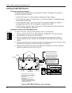
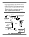
Installing 5800 Series Transmitters
To
be sure reception of the transmitter's signal at the proposed mounting location is
adequate, perform a Go/No Go Test in the TESTING the SYSTEM section.
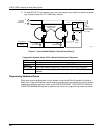
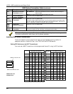
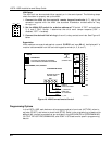
Setting DIP Switches on the 5827 Transmitter(s)
You must set a 5827 Transmitter to the programmed House ID, using its DIP switches.
DIP SWITCH POSITION
12345
1 ----UP
2 ---UP-
3 - - - UP UP
4--UP--
5--UP-UP
6--UPUP-
7 - - UPUPUP
8 -UP---
9 - UP - - UP
10 - UP - UP -
11 - UP - UP UP
12 - UP UP - -
13 - UP UP - UP
14 - UPUPUP -
15 - UPUPUPUP
16UP----
DIP SWITCH POSITIONHOUSE
ID
12345
17 UP - - - UP
18 UP - - UP -
19 UP - - UP UP
20 UP - UP - -
21 UP - UP - UP
22 UP - UP UP -
23 UP - UPUPUP
24 UP UP - - -
25 UP UP - - UP
26 UP UP - UP -
27 UP UP - UP UP
28 UP UP UP - -
29 UP UP UP - UP
30 UP UP UP UP -
31 UP UP UP UP UP
SWITCH UP FOR "ON"
SWITCH DOWN FOR "OFF"
SHOWN SET FOR
HOUSE ID # 30