


4–1
SECTION 4
Basic Hardwired Zones 1–6
••••••••••••••••••••••••••••••••••••••••••••••••••
In This Section
♦
Installing the Hardwired Zones
♦
Programming Hardwired Zones
••••••••••••••••••••••••••••••••••••••••••••••••••
Installing the Hardwired Zones
Common Characteristics for Zones 1–6
•
Response time from 300 - 500 milliseconds (400 milliseconds nominal).
•
Zone 3 can be programmed (in field
✱
52) for normally-closed sensor fast response
(10mSec max) to an open (suitable for vibration type contacts). Default response is
400mSec nominal, which should be used for most standard contacts.
•
EOLR supervised zones support both open-circuit and closed-circuit devices.
•
As many 4-wire smoke detectors as can be powered from Aux Power on the control (on
zone 5).
U
L
4-Wire Smoke/Combustion detectors are
not
permitted in UL installations.
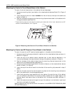
Wiring Burglary and Panic Devices to Zones 1–6
To wire burglary and panic devices to zones 1-6, perform the following steps, referring to
Figure 17. VISTA-10SE Summary of Connections
on the inside back cover of this manual.
1. Connect sensors/contacts to the hardwired zone terminals (8 through 16). See the
Summary of Connections diagram.
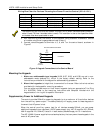
2. Connect closed circuit devices in series in the high (+) side of the loop. The EOL resistor
must be connected in series with the devices, following the last device. See the Summary
of Connections diagram.
3.
Connect open circuit devices in parallel across the loop. The 1000 ohm EOLR must be
connected across the loop wires
at the last device.
If the EOLR is not at the end of the loop, the zone will not be properly supervised, and the
system may not respond to an open circuit on the zone.
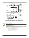
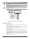
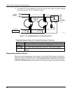
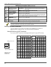
Wiring 4-Wire Smoke/Combustion Detectors on Zone 5
The system will support as many 4-wire detectors as can be powered from Auxiliary Power
on the control on zone 5. Refer to the detector’s instructions for complete details regarding its
proper installation and operation.
1. Connect 12-volt power for the detectors from Auxiliary Power terminals
4
and
5
(which
will interrupt power for fire alarm reset). Observe proper polarity when connecting
detectors. See
Figure 7
.
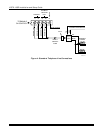
2. Connect detectors (including heat detectors, if used) across terminals of zone 5. All
detectors must be wired in parallel.
Remove 1000 ohm EOL resistor if connected across the zone terminals. You must connect the
EOL resistor across the loop wires at the last detector.