Section 3 - Installing Remote Keypads
3-3
Keypads powered from supplies that do not have a backup battery
will not function
when AC
power is lost. Therefore, be sure to power at least one keypad from the Control's auxiliary
power output.
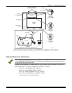
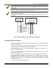
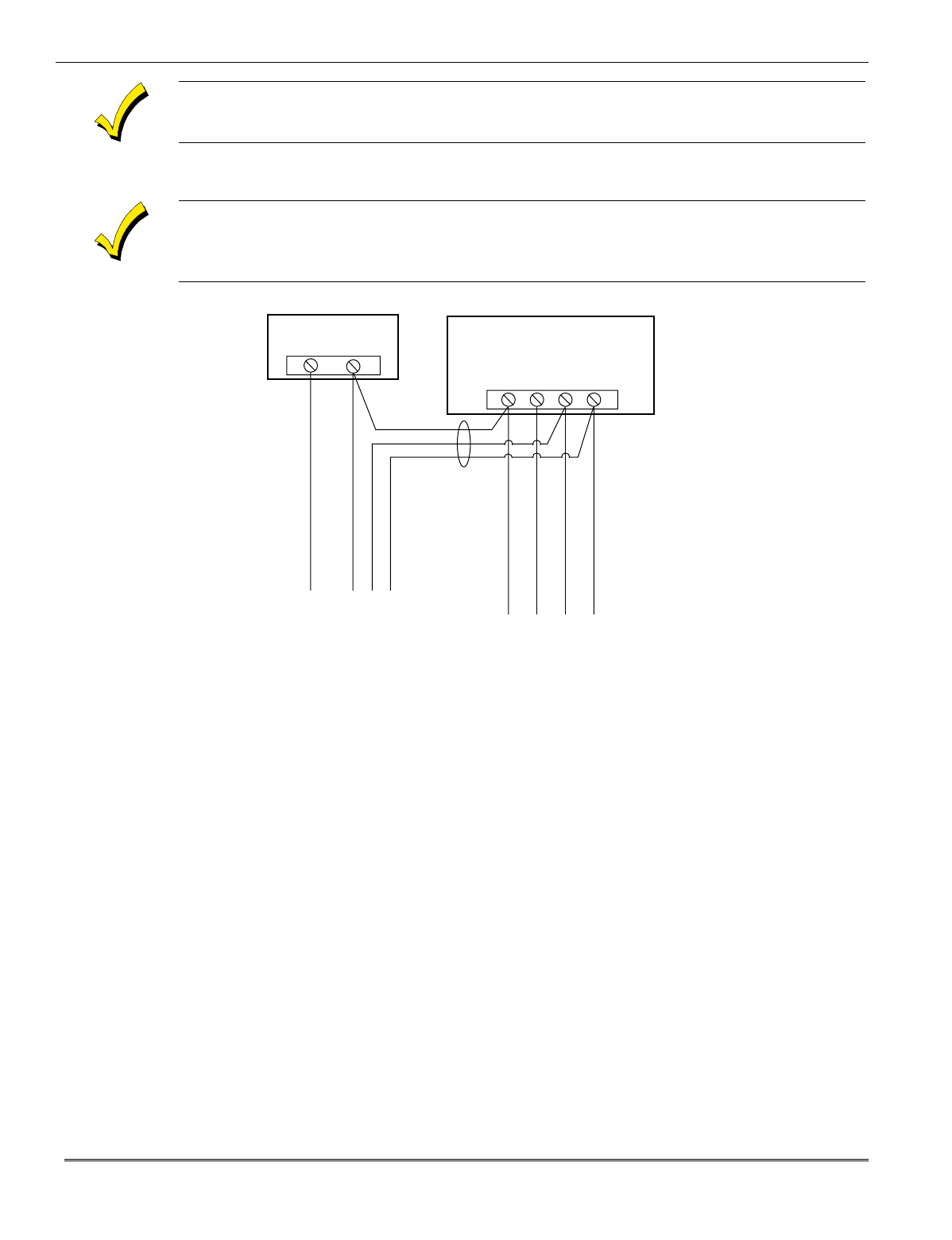
Connect the additional keypads as shown in Figure 6, using the keypad wire colors shown. Be
sure to observe the current ratings for the power supply used.
Make connections directly to the screw terminals as shown in
Figure 6
. Make no connection to
the keypad blue wire (if present).
Be sure to connect the negative (–) terminal on the Power Supply unit to terminal 4 (AUX
–
) on
the control.
+
–
+
456 7
SUPPLEMENTARY
POWER SUPPLY
–
CONTROL TERMINAL STRIP
AUX.
AUX. DATA
IN
DATA
OUT
IMPORTANT:
MAKE THESE
CONNECTIONS
DIRECTLY TO
SCREW
TERMINALS AS
SHOWN.
TO KEYPAD RED WIRE
TO KEYPAD BLK WIRE
TO KEYPAD YEL WIRE
TO KEYPAD GRN WIRE
TO KEYPAD BLK WIRE
TO KEYPAD RED WIRE
TO KEYPAD GRN WIRE
TO KEYPAD YEL WIRE
V10SE-008-V0
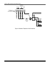
Figure 6. Using a Supplementary Power Supply for Keypads
Preliminary Checkout Procedure
If you want to check that the system is working before connecting field wiring from zones and
devices, do the following:
1. Temporarily connect a 1000 ohm end-of-line resistor across each of the basic hardwire
zones 1–6, as shown in the Summary of Connections diagram.
Without actual zone wiring or EOL resistors connected, the keypads in the system will not
display the “Ready” message.
2. Power-up the system temporarily by plugging the AC transformer (previously wired to the
control) into a 120VAC outlet.
3. Busy
–
Standby (on alpha keypads) or
dI
(on fixed-word keypads) will be displayed.
After approximately 1 minute*, the green READY LED (or POWER LED on some types of
keypads) should light, and the word "
READY"
(on fixed-word keypads) or the words
"
DISARMED...READY TO ARM"
(on alpha keypads) should be displayed, indicating the system
is functioning properly.
* To bypass the 1-minute delay, press # + 0.


