


VISTA-10SE Installation and Setup Guide
6-2
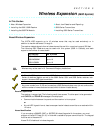
4204 Setup
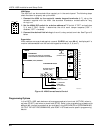
1 2 3 4 5
OFF ON
ON
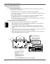
The 4204 unit can be mounted either remotely or in the control panel. The following steps
should be taken to properly set up the 4204:
1. Connect the 4204 to the control's remote keypad terminals (4–7), using the
connector supplied with the 4204. Use standard 4-conductor twisted cable for long
wiring runs.
2. Set the 4204's DIP switch for a device address of "1" (switch 2 "OFF" and switches
3, 4, and 5 "ON"). Switch 1 determines the unit's cover tamper response ("ON" =
disabled, "OFF" = enabled).
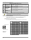
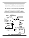
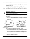
3. Connect the desired field wiring to the unit's relay contact terminals. See Figure 10
below.
Supervision
4204 modules are supervised against removal. CHECK and zone 09 will be displayed if a
module is disconnected from the control’s keypad terminals (4, 5, 6, and 7).
TB2
121110
9
87654321
DATA IN
FROM CONTROL
(–) GROUND
DATA OUT
TO CONTROL
(+) 12V
YEL
BLK
GRN
RED
13 14 15 16
DIP SWITCH
FOR SETTING DEVICE ADDRESS
AND ENABLING/DISABLING TAMPER
COVER TAMPER (REED) SWITCH
TB1
4204
4-PIN KEYPAD PLUG
RELAY
3
RELAY
2
RELAY
1
RELAY
4
TYPICAL
(SHOWN "OFF")
EITHER OR BOTH
CAN BE USED
C
NC
NO
C
NC
NO
C
NC
V10SE-016-V0
NC
NO
C
NC
NO
Figure 10. 4204 Connections to Control
Programming Options
In the VISTA-10SE, each device must be programmed as to how to act (ACTION), when to
activate (START), and when to de-activate (STOP). Refer to the programming procedures for
✱
80 and
✱
81 interactive modes that are provided in the MECHANICS of PROGRAMMING,
OUTPUT DEVICE PROGRAMMING, and ZONE LISTS sections for specific programming
details.