


Section 2 - Installing the Control
2-3
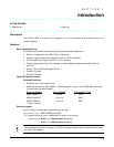
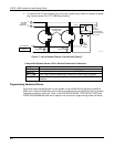
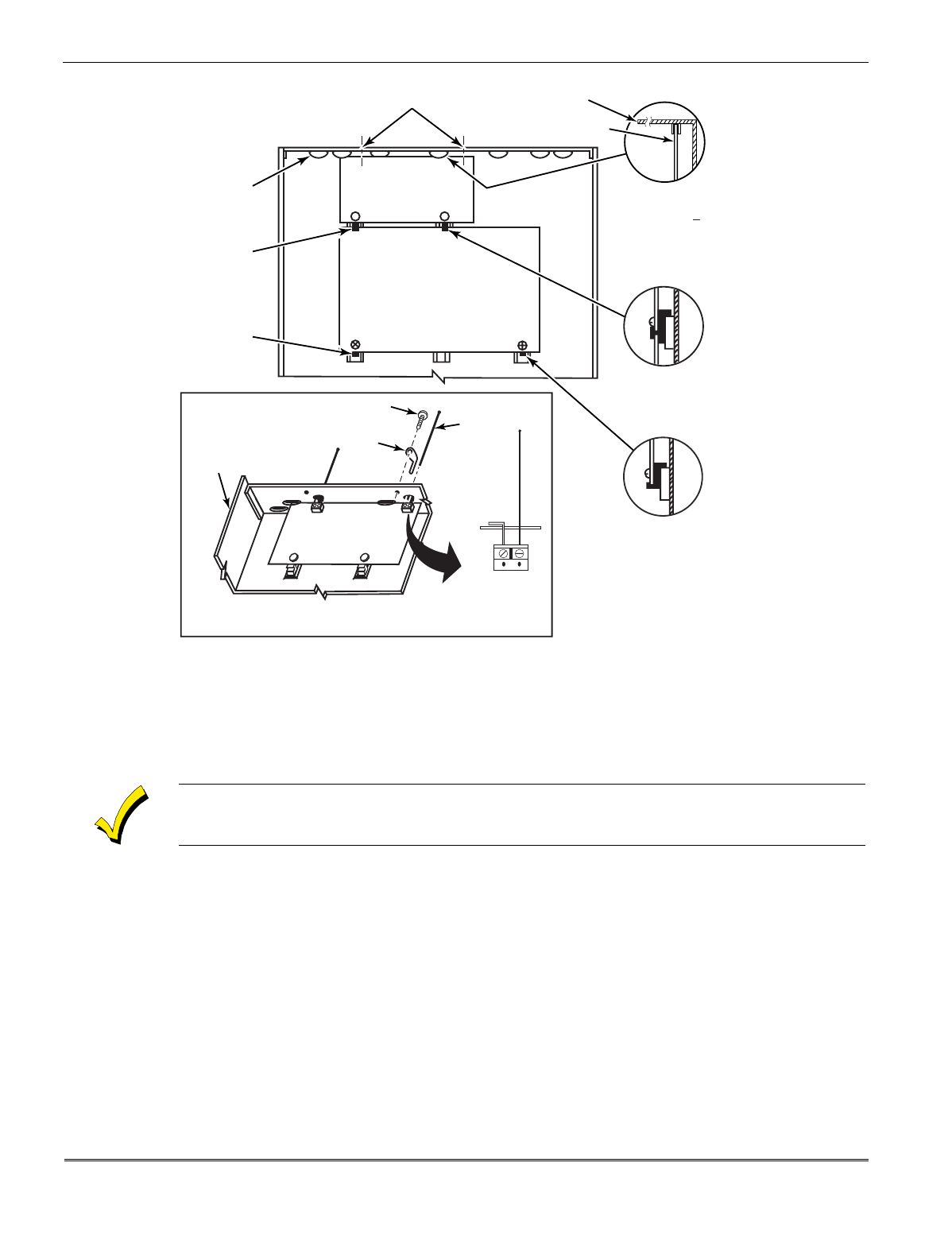
MOUNTING
CLIP
CABINET
DETAIL D
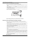
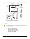
ANTENNA AND GROUNDING LUG INSTALLATION
ANTENNA
MOUNT
(2 PLACES)
ANTENNA
(2)
SCREW
(2)
MOUNTING
CLIP
CONTROL
CIRCUIT
BOARD
BOARD
SUPPORTING
SLOTS
HOLES FOR ANTENNAS
AND GROUNDING LUGS
RECEIVER CIRCUIT BOARD
(See Detail D)
++
++
RCVR BRD
DETAIL A
SIDE VIEW
OF BOARD
SUPPORTING SLOTS
DETAIL B
SIDE VIEW
OF MOUNTING
CLIP
DETAIL C
SIDE VIEW
OF MOUNTING
CLIP
GROUNDING
LUG
(2)
V10SE-004-V0
CIRCUIT BOARD
CABINET
Figure 3. Mounting the PC Board and RF Receiver Together in the Cabinet
Standard Phone Line Connections
The wiring connections shown here are not applicable if a 4285/4286 VIP Module is used. Refer
to the
4285/4286 VIP MODULE
section for information regarding phone line connections, which
are different than those shown here.
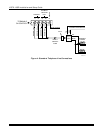
Connect incoming phone line and handset wiring to the main terminal block via an RJ31X
jack (CA38A jack in Canada) as follows and as shown in Figure 4.
Term. 17: Local Handset (TIP – Brown*).
Term. 18: Local Handset (RING – Gray*).
Term. 19: Incoming Phone Line (TIP – Green*).
Term. 20: Incoming Phone Line (RING – Red*).
*
Colors of wires in Direct Connect Cord.