


6–1
SECTION 6
Relay Output Devices
••••••••••••••••••••••••••••••••••••••••••••••••••
In This Section
♦
Relay Device Basics
♦
4204 Relay Modules
♦
Programming Options
••••••••••••••••••••••••••••••••••••••••••••••••••
Relay Device Basics
Relays are programmable switches that can be used to perform many different functions.
They can be used to turn lights on and off, control sounders, or for status indications. In this
system, each relay must be programmed as to how to act (ACTION), when to activate
(START), and when to deactivate (STOP). Each of these is described below.
The control supports a total of 4 output relays.
The 4204 Relay modules provide Form C (normally open and normally closed) contacts.
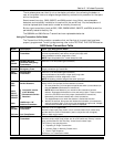
In
✱
80 and
✱
81 interactive modes, a series of keypad prompts will request entries for
programming of the Relay outputs used in the system. Refer also to “OUTPUT RELAY
DEVICE WORKSHEET FOR
✱
80 AND
✱
81 INTERACTIVE MODES” in the blank
programming form provided in the separate Programming Form manual.
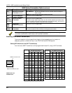
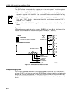
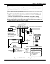
4204 Relay Modules
4204 Relay Unit (if installed in cabinet)
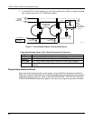
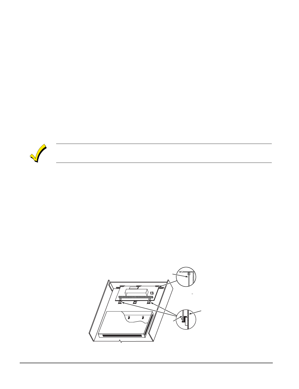
1. Insert self-tapping screws (provided) in two adjacent raised cabinet tabs. Leave the heads
projecting 1/8".
2. Hang the unit on the screw heads via two of the slotted holes at the rear of its housing, as
shown in
Figure 9
below.
3. The 4204's cover can be left off if the unit's DIP switch is set with its position 1 "ON" (to
the right) as shown in its instructions. The tamper-protected cover is necessary for
installations outside of the control's cabinet.
+
+
CIRCUIT BOARD
DETAIL B
SIDE VIEW
OF MOUNTING
CLIPS
DETAIL A
SIDE VIEW
OF BOARD
SUPPORTING
SLOTS
CIRCUIT
BOARD
V10SE-003-V0
CABINET
Figure 9. Mounting the PC Board in the Cabinet with a 4204 Relay Unit