


94 SCXG-SVX01B-EN
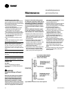
Variable Frequency Drive (VFD)
The VFD access panel is hinged to allow
service access to the fan motor and belt
drive components that are located behind
it. To swing the panel open:
• Remove the unit center cover panel to
the left of the VFD panel.
• Remove and discard the sheet metal
shipping screws along the top and
bottom edges of the VFD panel.
• Disconnect the communications cable
from the keypad on the VFD door panel.
• Turn the two slotted-head fasteners on
the right edge of the VFD panel fully
counterclockwise.
• Pull on the handle to swing the panel
180°.
To close and reattach the panel, reverse
the procedures listed above.
Note: To secure the panel in the open
position during service procedures, attach
the chain mounted to the cabinet frame
behind the unit center cover panel to the
chain retainer notch on the edge of the VFD
panel.
Note: Verify that all wires are in their proper
position and not rubbing before replacing
the panel.
Note: Panel weight rating = 225 lbs. total,
including factory-installed components.
Supply Fan
Fan Drive
Perform the following procedures
according to the “Periodic Maintenance
Check List”.
ƽƽ
ƽƽ
ƽWARNING
Hazardous Voltage w/Capaci-
tors!
Disconnect all electric power, including
remote disconnects before servicing.
Follow proper lockout/tagout proce-
dures to ensure the power cannot be
inadvertently energized. For variable
frequency drives or other energy storing
components provided by Trane or others,
refer to the appropriate manufacturer’s
literature for allowable waiting periods
for discharge of capacitors. Verify with an
appropriate voltmeter that all capacitors
have discharged. Failure to disconnect
power and discharge capacitors before
servicing could result in death or serious
injury.
Note: For additional information regard-
ing the safe discharge of capacitors, see
PROD-SVB06A-EN or PROD-SVB06A-FR.
1. Rotate the fan wheel to ensure it turns
freely in the proper direction and is not
rubbing on the fan housing, inlet, or inlet
guide vanes. If necessary, center the
fan wheel again.
2. Check the position of both shafts. Fan
and motor shafts should operate
parallel to each other for maximum belt
and bearing life. Shim as necessary
under the motor or fan bearings to
obtain proper alignment.
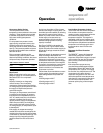
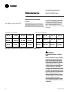
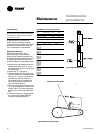
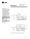
3. Check the fan motor sheave alignment
with straight edge or a tightly pulled
string. For sheaves of different widths,
place a string in the center groove of
Figure M-MP-4. Fan shaft and motor sheave alignment
each sheave and pull it tight for a center
line. See Figure M-MP-6 for
recommended torques.
4. Once the sheaves are properly aligned,
tighten sheave set screws to proper
torque. See Tables M-MP-1 and M-MP-2
for recommended torques.
5. Check belt tension. Refer to the
“Measuring Belt Tension” section.
6. If required, adjust belt to the minimum
recommended tension. Refer to
“Adjusting Belt Tension” section.
7. Retighten bearing set screws to the
proper torques after aligning the
sheaves. See Tables M-MP-1 and M-
MP-2 for proper torques.
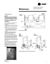
8. Check the fan bearing locking collars
for tightness on the shaft. To tighten the
locking collar, loosen the set screw and
slide the collar into its proper position
over the extended end of the inner
case. Tighten the set screw to the
torque value in Tables M-MP-1 and M-
MP-2.
9. During air balancing, verify the sheave
alignment, belt tension, and that the
shaft is parallel.
Maintenance
maintenance
procedures