


74 SCXG-SVX01B-EN
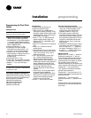
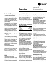
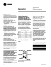
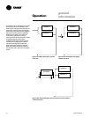
Figure O-GI-2. Velocity pressure transducer/
solenoid assembly
PURGE sequence “D”
This sequence can purge the air out of a
building before coming out of unoccupied
mode of operation in a VAV system. Also,
it can be used to purge smoke or stale air.
• Supply fan – on
• Supply fan VFD – on (60 hz)
• Inlet guide vanes/VAV boxes – open
• Outside air damper – open
• Heat – all stages – off, modulating heat
output at 0 vdc
• Occupied/Unoccupied output –
energized
• VO relay – energized
• Exhaust fan (field-installed) - on
• Exhaust damper (field-installed) - open
PURGE with duct pressure control “E”
This sequence can be used when supply
air control is required for smoke control.
• Supply fan – on
• Supply fan VFD – on (if equipped)
• Inlet guide vanes – controlled by supply
air pressure control function with
supply air pressure high limit disabled
• Outside air dampers – open
• Heat – all stages – off, hydronic heat
output at 0 vdc
• Occupied/unoccupied output – energized
• VO relay – energized
• Exhaust fan (field-installed) - on
• Exhaust damper (field-installed) - open
Note: Each system (cooling, exhaust,
supply air, etc.) within the unit can be
redefined in the field for each of the five
sequences, if required. Also the definitions
of any or all of the five sequences may be
locked into the software by simple key
strokes at the human interface panel. Once
locked into the software, the sequences
cannot be changed.
Trane IntelliPak Lon-Talk
Communication Module (LCI-I
Option used on units with
Trane ICS
TM
or 3rd party
Building AutomationSystems)
The LonTalk Communication Interface
module expands communications from
the unit UCM network to a Trane Tracer
Summit
TM
or a 3rd party building
automation system, utilizing LonTalk, and
allows external setpoint and
configuration adjustment and monitoring
of status and diagnostics.
general
information
Exhaust/Comparative
Enthalpy (ECEM ) Module -
Option used on units with
comparative enthalpy option
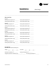
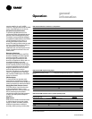
The exhaust/comparative enthalpy
module receives information from the
return air humidity sensor, and the RTM
outside air temperature sensor and
outside air humidity sensor, the outside
air humidity sensor and temperature
sensor to utilize the lowest possible
enthalpy level when considering
economizer operation. In addition, it
receives space pressure information to
maintain the space pressure within the
setpoint control band. Refer to the Figure
O-GI-1 for humidity vs. voltage values.
Ventilation Control Module
(VCM) - Available only with
Traq™ Damper Option
The ventilation control module (VCM) is
located in the airside economizer section
of the unit and linked to the unit’s UCM
network. Using a velocity pressure
transducer/solenoid (pressure sensing
ring) in the fresh air section allows the
VCM to monitor and control fresh air
entering the unit to a minimum airflow
setpoint. See Figure O-GI-2 for a detail
view of the velocity pressure transducer/
solenoid assembly.
An optional temperature sensor can be
connected to the VCM to enable control
of a field installed fresh air preheater.
Also, a field-provided CO
2
sensor can be
connected to the VCM to control CO
2
reset. The reset function adjusts the
minimum cfm upward as the CO
2
concentrations increase. The maximum
effective (reset) setpoint value for fresh
air entering the unit is limited to the
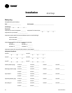
system’s operating cfm. Table O-GI-5 lists
the minimum outside air cfm vs. input
voltage.
Table O-GI-5. Minimum outside air setpoint
w/VCM module and Traq™ sensing
Unit Input Volts CFM
SXWG 20 0.5 - 4.5 vdc 6,350-8,500
SXWG 25 0.5 - 4.5 vdc 7,250-10,625
SXWG 30 0.5 - 4.5 vdc 7,250-12,750
SXWG 35 0.5 - 4.5 vdc 7,250-14,875
SXRG 20 0.5 - 4.5 vdc 7,250-8,500
SXRG 25 0.5 - 4.5 vdc 7,250-10,625
SXRG 32 0.5 - 4.5 vdc 7,250-13,600
Figure O-GI-1. ECEM relative humidity vs.
voltage
Operation