


16 SCXG-SVX01B-EN
Installation
pre-installation
considerations
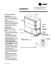
Split-Apart Unit Assembly
1. Ensure the tagging information on the
fan section nameplate matches that on
the compressor nameplate.
2. Remove the connector brackets
holding the the sheet metal shipping
cover on compressor section. Retain
brackets and screws.
3. Remove shipping cover from the
compressor section and verify the ship-
with packge contains:
• suction and discharge line couplings
• insulation
• sheet metal screws
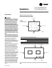
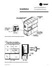
4. Lift fan section onto the compressor
section using the rigging method in
Figure I-PC-8 on page 13.
5. Remove skid from the fan section,
placing the fan section onto the
compressor section. Reference Figure I-
PC-9.
6. Install the connection brackets with the
sheet metal screws (referenced in step
2) on all sides of the unit. Reference
Detail “A” in Figure I-PC-9.
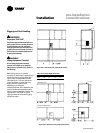
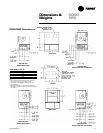
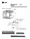
7. Remove the unit panels labeled RU and
RL in Figure I-PC-10 on page 17. To
remove panels, first remove the four
shipping screws located in the corner of
each panel. Next, turn the remaining
1
/
4
turn fasteners to the unlatch position.
The panel is supported by a “lip”
channel. So, lift the panel up and off the
unit to remove it. See Detail “A”in
Figure I-PC-9.
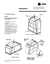
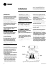
8. Connect the drain hose to the drainpan
outlet fitting and secure it with the drain
hose clamp provided.
9. Circulate nitrogen thoughout
refrigerant circuits.
10. Unbraze and remove the caps on the
discharge and suction lines in both the
compressor and fan sections.
11. Install and braze discharge and
suction line couplings.
12. Insulate discharge and suction lines
with the insulation provided.
13. Remove panel FLR and open the
bottom control panel door, FLL. Pull the
fan motor leads (coiled in the fan
section) through the knockout in the
bottom of the fan section to the control
panel. Ensure that the bushing is
installed in the hole to prevent the
wires from chafing. Refer to the unit
wiring diagrams to connect the fan
motor leads properly and ensure
correct phase sequencing.
IntelliPak Units(UCM) Only
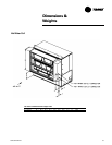
14. Remove panels FML, FMM, and FMR.
15. Pull the circular plug connector (CPC)
from the compressor section through
the knockouts into the fan section.
Install the bushings (provided on the
wiring harnesses) in the knockouts.
16. Using the CPC wiring diagram,
connect the male CPC to the female
CPC in the top control panel.
17. If the unit has the mixed air
temperature option, route the capillary
tube on back of the filter rack.
Units with Thermostat Only
18. Remove panel FMR. See Note 1 on
Figure I-PC-10.
19. Pull frost protection wires from the
bottom control panel throughknockouts
in bottom of fan section. Route wires to
the appropriate frost protection
switches on the evaporator coil.
Reference the unit wiring diagrams to
connect frost protection wiring
connectors.
Air-Cooled Units Only:
20. Route the refrigerant circuit wires for
circuits 1 and 2 from the bottom control
panel through the knockouts to the
solenoid valves. The solenoid valves
are located in the liquid refrigerant
lines on the right-hand side of the unit.
Refer to the unit wiring diagrams to
make splice connections.