


SCXG-SVX01B-EN 67
Unit Startup Procedures
ƽƽ
ƽƽ
ƽ
WARNING
Hazardous Voltage w/Capaci-
tors!
Disconnect all electric power, including
remote disconnects before servicing.
Follow proper lockout/tagout proce-
dures to ensure the power cannot be
inadvertently energized. For variable
frequency drives or other energy storing
components provided by Trane or others,
refer to the appropriate manufacturer’s
literature for allowable waiting periods
for discharge of capacitors. Verify with an
appropriate voltmeter that all capacitors
have discharged. Failure to disconnect
power and discharge capacitors before
servicing could result in death or serious
injury.
Note: For additional information regard-
ing the safe discharge of capacitors, see
PROD-SVB06A-EN or PROD-SVB06A-FR.
Pre-Startup Checklist
1. Verify electrical connections are tight.
2. Water-cooled: Access the liquid line
service valves. Verify the liquid line
service valve is open at startup.
Note: Each compressor suction line
contains a low pressure sensor that will
shut the compressor down in low pressure
situations. See Table O-SO-2.
3. Ensure system components are
properly set and installed.
4. Inspect all ductwork and connections.
5. Remove compressor and fan
assembly tie down bolts. On 20 - 38 ton
units, do not remove the fan assembly
shipping blocks. Tie down bolts if the fan
speed is 750 rpm or less.
6. Ensure fan rotation is in the direction of
the arrow on the fan housing. If it is
incorrect, verify the incoming power
phasing is correct. Switch wires on the
fan contact to properly phase fan if
necessary.
7. Check the fan belt condition and tension.
Adjust the tension if belts are floppy or
squeal continually. Replace worn or
fraying belts in matched sets.
Startup
ƽƽ
ƽƽ
ƽ
WARNING
Live Electrical Components!
During installation, testing, servicing and
troubleshooting of this product, it may
be necessary to work with live electrical
components. Have a qualified licensed
electrician or other individual who has
been properly trained in handling live
electrical components perform these
tasks. Failure to follow all electrical safety
precautions when exposed to live
electrical components could result in
death or serious injury.
NOTICE
Compressor Damage!
Never manually or automatically pump
down system below 7 psig. This will
cause the compressor to operate in a
vacuum and result in compressor
damage.
To start the unit, complete the following
steps in order.
1. Apply power to the unit. Close the unit
disconnect switch option.
2. Make sure the liquid line service valves
are open on water cooled units.
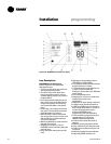
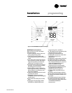
3. Adjust setpoints at the HI.
Note: A sufficient cooling load must be
visible to refrigerant circuit controls for
mechanical refrigeration to operate. If
necessary, temporarily reduce the dis-
charge air setpoint to verify the refrigeration
cycle operation.
4. Check voltage at all compressor
terminals to ensure it is within 10% of
nameplate voltage.
5. Check voltage imbalance from these
three voltage readings at each
compressor. Maximum allowable
voltage imbalance, phase to phase is
2%.
6. Check amp draw at compressor
terminals. RLA and LRA is on the unit
nameplate.
startupInstallation
7. Measure amp draw at evaporator fan
motor terminals. FLA data is on the
motor nameplate.
8. After the system has stabilized (15 to 30
minutes), check and record operating
pressures and temperatures for all
circuits.
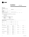
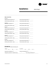
Using the startup log on the following
pages, establish nominal conditions for
consistent measurements as follows:
• Leaving air greater than 60°F
• Entering air temperature = 70 to 90°F
• Entering water temperature > 60°F
• Inlet guide vanes at least halfway open
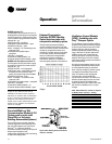
With all compressors running at full load:
1. Compute superheat from the suction
line pressure and temperature at the
compressor on each circuit. Adjust the
thermal expansion valve settings if
necessary. Superheat should be
between 12 and 17°F.
2. Inspect refrigerant flow in the liquid line
sight glass. Flow should be smooth and
even, with no bubbles once the system
has stabilized.
Normal startup will occur provided that
Tracer Summit is not controlling the
module outputs or the generic BAS is not
keeping the unit off. To prevent Tracer
Summit from affecting unit operation,
remove Tracer
wiring and make required
changes to setpoint and sensor sources.
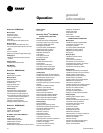
Operating & Programming Instructions
Reference the
IntelliPak Self-Contained
Programming Guide, PKG-SVP01B-EN,
for available unit operating setpoints and
instructions.
A copy ships with each unit.
For units with the VFD option, reference
the installer guide that ships with each
VFD.