


SCXG-SVX01B-EN 35
pre-startup
requirements
Installation
Pre-Startup Procedures
ƽƽ
ƽƽ
ƽ
WARNING
Hazardous Voltage w/Capacitors!
Disconnect all electric power, including
remote disconnects before servicing.
Follow proper lockout/tagout proce-
dures to ensure the power cannot be
inadvertently energized. For variable
frequency drives or other energy storing
components provided by Trane or others,
refer to the appropriate manufacturer’s
literature for allowable waiting periods
for discharge of capacitors. Verify with an
appropriate voltmeter that all capacitors
have discharged. Failure to disconnect
power and discharge capacitors before
servicing could result in death or serious
injury.
Note: For additional information regard-
ing the safe discharge of capacitors, see
PROD-SVB06A-EN or PROD-SVB06A-FR.
Before starting up units perform the
following procedures to ensure proper
unit operation.
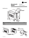
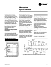
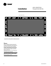
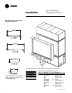
Figure I-PR-2. Fan isolator locations.
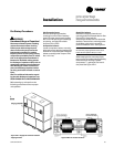
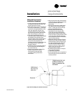
Figure I-PR-1. Supply fan horizontal isolation
shipping bracket.
Unit Protective Covers
Remove the shipping protection
coverings from the human interface
panel (HI) at the control panel, the filter
box (or air inlet opening), the discharge
air opening, and optional variable
frequency drive (VFD).
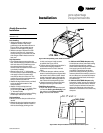
Compressor Isolators
Loosen compressor isolator mounting
bolts and remove shipping bracket from
beneath the compressor feet. Retighten
isolator mounting bolts. Torque to 18 ft.
lbs. (+ 2 ft. Lbs.)
Supply Fan Isolators
Remove the shipping channels and
mounting bolts from beneath the fan. See
Figure I-PR-1. Open both fan
compartment access doors to access the
channels. There are four mounting points
for 20-38 ton units and six mounting
points for 40-80 ton units. See Fig I-PR-2.
Note: For 20-38 ton units, do not remove the
fan assembly shipping blocks and tie down
bolts if the fan speed is 750 rpm or less.
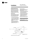
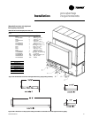
While keeping the fan mounting frame
level, turn the fan isolator height adjusting
bolts until the fan housing P-gasket
compresses
1
/
4
” against the roof transi-
tion piece. See Figure I-PR-1.