


38 SCXG-SVX01B-EN
pre-startup
requirements
Static Pressure Transducer
Installation (VAV units only)
Supply air static pressure controls the
inlet guide vane and inverter options. A
static pressure head assembly ships
separate in the control panel for field
installation in the supply air duct work.
The installer is responsible for providing
pneumatic tubing.
Transducer Location
Place the head assembly in an area of the
ductwork that will provide an average
and evenly distributed airflow pattern.
Use the following guidelines to determine
an appropriate installation location.
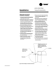
1. Locate the static head assembly about
2
/
3
to
3
/
4
of the way down the longest
duct run, in an area approximately 10
duct diameters downstream and 2 duct
diameters upstream of any major
interferences, turns, or changes in duct
diameter.
2. When installing pneumatic tubing
between the head assembly and
transducer in the control panel, do not
exceed 250 feet for
1
/
4
” OD tubing or
500 feet for
3
/
8
” OD tubing.
Installing the Transducer
Complete the following procedure to
properly install the inlet guide vane static
pressure transducer.
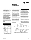
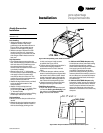
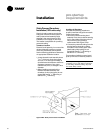
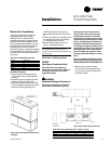
1. Mount the pressure sensing head
assembly in the duct so that the sensing
tip is in the middle of the duct so that it
will provide a proper pressure
measurement. See Figure I-PR-6.
2. Connect the pneumatic tubing from the
sensing head to the push-on tubing
connection in the control panel. Use a
plastic static pickup tubing. Do not
exceed 250 feet for
1
/
4
“ OD tubing or
500 feet for
3
/
8
” OD tubing.
The transducer inside the control panel
picks up low side or reference pressure.
Note: If plastic tubing pulls away from a
connection, trim it back before replacing it
on the fitting. Stretched tubing may leak
and cause faulty control.
Installation
Figure I-PR-6. Static pressure sensor installation