


88 SCXG-SVX01B-EN
Compressors
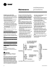
Units use two sizes of hermetic scroll
compressors, 10 and 15 hp, and can use
from two to six compressors. When
viewing the front of the unit, compressors
are identified A through B from left to
right. The second compressor from the
left, or B compressor, is always the first to
come on, unless locked out for a
malfunction or shut off on frost protection.
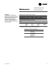
Refer to Table O-SO-1 for compressor
cycling stages and Table O-SO-3 on page
78 for percent cooling capacity by stage.
The control system logic permits com-
pressor operation only after the supply
fan is on. If the supply fan shuts down,
compressors will not operate. Units
without head pressure control (units with
intermediate piping packages) will lock
out mechanical cooling when the entering
condenser water temperature falls below
54°F. Mechanical cooling will resume
when the entering condenser water
temperature exceeds 58°F.
When there are more than two compres-
sors in an air cooled unit, the first two
sequence of
operation
compressors are manifolded together. If
there are four compressors, the second
two are manifolded.
Compressor Cycling
Compressors cycle to maintain the
operating state required by the
temperature controls. In the event of a
compressor failure, the next available
compressor turns on. Refer to Table O-
SO-1 for compressor cycling by unit
model and tons.
During normal conditions, compressors
will not shut off until they have been on
for at least three minutes and will not turn
on until they have been off for at least
three minutes. Normal operating condi-
tions are established on an individual
compressor basis. When a compressor
starts, its timer also starts. The compres-
sor evaporator circuit frost protection can
override the “minimum” timer and
reduce the five minute minimum re-
quired time period.
When the unit is powered up, or manually
reset there will be a three to eight minute
delay before the first compressor may be
turned on as requested by the unit
temperature control algorithm.
Compressor Lead/Lag Operation
Compressor lead/lag is a user-selectable
feature at the HI panel and is available on
all units. After each request for
compressor operation, the lead
refrigeration circuit or compressor
switches, thereby causing a more
equitable or balanced run time among
compressors.
When lead/lag is enabled, each time the
system cycles, it will alternate between
the standard compressor staging and the
lead/lag staging. Using Table O-SO-1, a
SXWG 30-ton unit will first stage com-
pressor B then A, then AB for first cycle
and A, then AB for the second cycle.
Appropriate condenser valves (water-
cooled and condenser fans (air-cooled)
will stage with appropriate compressors
to maintain saturated condensing
temperature. Enabling lead/lag may drop
a cooling stage when compared to
standard staging. See Table O-SO-1 for
compressor staging.
Operation
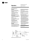
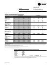
Table O-SO-1. Compressor Stages.
Unit Refrigerant Compressor HP Standard Lead/Lag SCM
Size Circuit Type by Stage Compressor Compressor or
Model # Digit 5 A B Staging Staging MCM
SXWG 20, 25 Independent 10 10 B/AB A/AB MCM
SXRG 20
SXWG 30 Independent 15 10 B/A/AB A/AB MCM
SXRG 25
SXWG 35 Independent 15 15 B/AB A/AB MCM
SXRG 32