


34 SCXG-SVX01B-EN
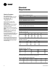
Selection Procedures
RLA = rated load amps
Compressor LRA = locked rotor amps
Fan motor LRA = locked rotor amps,
N.E.C. table 430 - 150
FLA = full load amps, N.E.C.
Table 430 - 150
Voltage utilization range is ±10%
Determination of minimum circuit
ampacity (MCA).
MCA = 1.25 x largest motor amps/VFD
amps (FLA or RLA) + the sum of the
remaining motor amps.
Determination of maximum fuse size
(MFS) and maximum circuit breaker size
(MCB).
MFS and MCB = 2.25 x largest motor
amps (FLA or RLA) + the sum of the
remaining motor amps.
For units with the dual power option,
there are two electrical circuits that need
calculations using the formulas above:
circuit #1 - fans
circuit #2 - compressors
If the rating value determined does not
equal a standard current rating of over
current protective device, use the next
lower standard rating for the marked
maximum rating.
Table ED-1. Number of Compressors per Unit
SCWG/SIWG 20 25 30 35
SCRG/SIRG 20 25 32
10 HP 2 2 1 -
15 HP - - 1 2
Table ED-2. SCWG/SIWG Compressor Motor Data
200V 460V 575V
HP RLA LRA RLA LRA RLA LRA
10 33.1 269 14.4 117 11.5 94
15 46.9 409 20.4 178 16.4 143
Table ED-3. SCRG/SIRG Compressor Motor Data
200V 460V 575V
HP RLA LRA RLA LRA RLA LRA
10 38.4 269 16.7 117 13.4 94
15 55.0 409 24.1 178 19.1 143
Table ED-4. Fan without VFD
200V 460V 575V
HP FLA LRA FLA LRA FLA LRA
5 16.1 105 6.7 46 5.4 37
7.5 25.0 152 10.8 66 8.2 54
10 32.9 193 14.2 84 11.4 66
15 44.8 290 20.3 126 16.2 102
20 61.0 373 25.0 162 20.0 132
25 74.0 469 31.0 204 24.2 162
Table ED-5. Fan with VFD
200V 460V
HP FLA LRA FLA LRA
7.5 13.8 152 10.6 66
10 32.2 193 14.2 84
15 48.3 290 21.0 126
20 61.9 373 27.6 162
25 78.2 469 34.0 204
Note: Values are at the maximum VFD input rating and not the reduced motor values.
Table ED-6. Electric Heat - Single Stage
SCWG/SIWG SCRG/SIRG Heat 200V 460V
Size Size Kw Amps Amps
20 20 16 44.8 19.6
25 25 20 55.6 24.2
30 - 24 66.8 29.0
- 32 26 72.4 31.6
35 - 28 78 34.0
Note: Electric heat amperage should not be considered when determining minimum circuit ampacity. The current of the
unit in the heating mode will not exceed the current of the unit in the cooling mode.
Table ED-7. CCRC/CIRC Condenser Electrical Data
Unit Size Rated MFS/
Tons Voltage # Fans FLA (ea.) LRA (ea.) MCA MCB
20, 29, 32 200 4 4.1 20.7 17.4 20
230 4 4.1 20.7 17.4 20
460 4 1.8 9.0 7.7 15
575 4 1.4 7.2 6.0 15
Note: All motors for CCRC/CIRC units are rated at 1 hp (.7457 kW).
Electrical
Requirements