


56 SCXG-SVX01B-EN
pre-startup
requirements
Installation
Connecting to Tracer Summit
ƽƽ
ƽƽ
ƽ
WARNING
Hazardous Voltage w/Capaci-
tors!
Disconnect all electric power, including
remote disconnects before servicing.
Follow proper lockout/tagout proce-
dures to ensure the power cannot be
inadvertently energized. For variable
frequency drives or other energy storing
components provided by Trane or others,
refer to the appropriate manufacturer’s
literature for allowable waiting periods
for discharge of capacitors. Verify with an
appropriate voltmeter that all capacitors
have discharged. Failure to disconnect
power and discharge capacitors before
servicing could result in death or serious
injury.
Note: For additional information regard-
ing the safe discharge of capacitors, see
PROD-SVB06A-EN or PROD-SVB06A-FR.
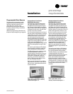
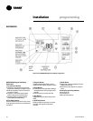
IntelliPak commercial self-contained
(CSC) units operate with Trane building
automation software, Tracer Summit
version 10.0.4 or later or any OS2
operating system.
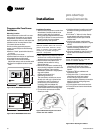
Note: Tape the non-insulated end of the
shield on shielded wire at the unit. Any
connection between the shield and ground
will cause a malfunction. If daisy-chained in
the unit, splice and tape the shields to
prevent contact with ground.
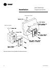
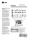
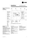
Communication Wiring
Note: Communication link wiring is a
shielded, twisted pair of wire and must
comply with applicable electrical codes.
An optional communication link provides
a serial communication interface (SCI)
between Tracer Summit and each
commercial self-contained (CSC) unit in
the system. The CSC system can have a
maximum of 12 CSC units per connection
link to Tracer Summit. Use a single 18
AWG shielded, twisted pair wire with
stranded, thinned copper conductors to
establish each communication link
between Tracer Summit and each unit.
Pre-Startup Checklist
Complete this checklist after installing the
unit to verify all recommended
installation procedures are complete
before unit start-up. This does not replace
the detailed instructions in the
appropriate sections of this manual.
Always read the entire section carefully
to become familiar with the procedures.
Receiving
Inspect unit and components for
shipping damage. File damage claims
immediately with the delivering carrier.
Check unit for missing material. Look
for ship-with drives, isolators, filters,
and sensors that are packaged
separately and placed inside the main
control panel, fan section, or
compressor section. See the “Receiving
and Handling” section.
Check nameplate unit data so that it
matches the sales order requirements.
Unit Location
Remove crating from the unit. Do not
remove the shipping skid until the unit is
set in its final position.
Ensure the unit location is adequate for
unit dimensions, ductwork, piping, and
electrical connections.
Ensure access and maintenance
clearances around the unit are
adequate. Allow space at the end of the
unit for shaft removal and servicing.
See the “Service Access” section.
Unit Mounting
Place unit in its final location.
Remove shipping skid bolts and skid.
If using isolators, properly mount unit
according to the isolator placement
sheet.
Remove shipping brackets on the
compressors and supply fan.
Remove the unit protective shipping
covers.
Component Overview
Verify the fan and motor shafts are
parallel.
Verify the fan and motor sheaves are
aligned.
Check the belt tension for proper
adjustment.
Ensure the fan rotates freely.
Tighten locking screws, bearing set
screws and sheaves.
Ensure bearing locking collars do not
wobble when rotated.
Ductwork
If using return ductwork to the unit,
secure it with three inches of flexible
duct connector.
Extend discharge duct upward without
change in size or direction for at least
three fan diameters.
Use a 3” flexible duct connection on
discharge ductwork.
Ensure trunk ductwork to VAV boxes is
complete and secure to prevent leaks.
Verify that all ductwork conforms to
NFPA 90A or 90B and all applicable
local codes
Water-Cooled Unit Piping
Verify the condensate drain piping is
complete for the unit drain pan. Install
and tighten the condensate “P” trap
drain plug.
Install water piping drain plugs,
economizer header, and condenser
vent plugs.
Make return and supply water
connections to the unit and/or waterside
economizer piping package with
recommended valves and piping
components. Refer to the “Water
Piping” section.
Install unions to allow waterside
maintenance.
Install cooling tower and standby
pumps.
Treat water to prevent algae, slime,
and corrosion.
Prevent refrigerant piping from rubbing
against other objects.
Air-Cooled Units Only
Connect refrigerant lines.
Install liquid line filter driers.
Units with Hydronic Heat
Verify the entering water temperature
sensor is installed upstream of the
hydronic coil.
Units with Electric Heat
Verify the supply air temperature
sensor is downstream of the electric
heat coil.