


86 SCXG-SVX01B-EN
sequence of
operation
Occupied Sequence
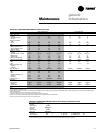
All setpoints can be adjusted using the HI
panel. Also, cooling/heating setpoints can
be adjusted in the zone, if using one of the
zone sensor options (BAYSENS020,
BAYSENS021, BAYSENS108,
BAYSENS110, BAYSENS019, or
BAYSENS074). For a complete list of unit
setpoint default values and ranges, see
the
IntelliPak
Self-Contained
Programming Guide, PKG-SVP01B-EN
.
Occupied Zone Temperature - Cooling
The unit transitions from unoccupied to
occupied when the occupied/unoccupied
input on the RTM is open for more than
five seconds after having been closed.
This input can be received from Tracer
Summit, the remote NSB zone sensor,
the timed override function, or a field
supplied contact. Dependent on unit
options and the HI programming, the
following sequence will occur:
• The unit will begin MWU and then
switch to the occupied mode after the
MWU setpoint is met.
• Purge will be enabled by Tracer Summit.
Then Tracer Summit will enable the
occupied mode.
• The unit will switch from unoccupied to
occupied control immediately.
Upon entering occupied mode,the IGV
option will close while the supply fan
remains on. The occupied/unoccupied
relay will de-energize.
Zone Temperature Control
(Unit Model Number Digit 9 = 4 or 5)
A zone sensor located directly in the
space sends input to the RTM while the
CV unit is in occupied cooling mode.
When the unit is in occupied cooling, the
RTM controls the zone temperature
within the cooling setpoint deadband by
modulating the economizer option and/or
staging mechanical cooling on and off as
required.
Supply Air Temperature Control
(Unit Model Number Digit 9 = 1, 2, 3, or 6)
When the VAV unit is in occupied cooling,
the RTM controls the supply air
temperature to the specified supply air
cooling setpoint by modulating the
economizer option and/or staging
mechanical cooling on and off as
required. The changeover relay contacts
(field supplied) must be open on units
with hydronic heat for cooling to operate.
Cooling
Upon entering occupied mode, the RTM
receives an input from either the HI, RHI,
Tracer Summit, or the GBAS to start the
supply fan. The RTM supply fan contacts
close and energize the supply fan
contactor. On VAV units with IGV, the fan
delays until the IGV fully close. When the
supply fan starts, the fan proving switch
closes, signaling the RTM that airflow is
established. Depending on unit options,
either the IGV will begin to drive open, the
VFD will ramp the fan, and/or the airside
economizer dampers will open to the
user-defined minimum position.
When a cooling request is sent to the
RTM from the zone sensor, the RTM
evaluates the system operating condi-
tions using the supply air and outdoor
temperature input before sending the
request to the MCM for mechanical
cooling. If outdoor conditions (tempera-
ture and humidity) are suitable or the
EWT is within specified setpoints, the
RTM will attempt to use “free cooling”
without using any compressors. The RTM
will use either the airside or waterside
economizer option. When outdoor air
conditions are not suitable, only mechani-
cal cooling will function and outside air
dampers will remain at their minimum
position. If the unit does not have an
economizer, mechanical cooling will
operate to satisfy cooling requirements.
Units With Economizer
If the entering condenser water
temperature (units with a WSE) or the
outside air enthalpy (units with an ASE) is
appropriate to use “free cooling,” the
economizer will attempt to satisfy the
cooling zone temperature setpoint.
Note: When using an ASE with economizer
enabled, O/A temperature enable can be
used instead of comparative enthalpy if the
O/A temperature falls below the economizer
setpoint.
Then compressors will stage on as
necessary to maintain supply air tem-
perature setpoint, which is user-defined
at the HI. Minimum on/off timing of
compressors prevents rapid cycling.
When both airside and waterside
economizers are on a single unit, priority
must be set at the HI. The economizer
with the highest priority attempts cooling
first. Once it is operating at its maximum,
and if additional cooling is necessary, the
other economizer enables before
mechanical cooling begins.
Cooling/Waterside Economizer
Waterside economizing enables when
the unit’s entering water temperature is
below the unit’s entering mixed air
temperature by 4°F plus the user
adjustable economizer approach
temperature. The approach temperature
default is 4°F.
Waterside economizing disables when
the unit’s entering water temperature is
not below the unit’s entering mixed air
temperature by at least the water
economizer approach temperature
(default value of 4°F). The economizer
acts as the first stage of cooling. If the
economizer is unable to maintain the
zone (CV units) or supply air (VAV units)
temperature setpoint, the compressor
module will bring on compressors as
required to meet the setpoint.
Cooling/Airside Economizer
On units with an airside economizer, a call
for cooling will modulate the fresh air
dampers open. The rate of economizer
modulation is based on deviation of the
zone temperature from setpoint; i.e., the
further away from setpoint, the faster the
fresh air damper will open. The first stage
of cooling will start after the economizer
reaches full open.
Note: The airside economizer will only
function freely if ambient conditions are
below the enthalpy control settings or
below the return air enthalpy if unit has
comparative enthalpy installed. If outside
air is not suitable for “economizing,” the
fresh air dampers drive to the minimum
open position. A field adjustable, factory
default setting at the HI panel or Tracer
Summit can provide the input to establish
the minimum damper position.
When outdoor air conditions are above
the setpoint or comparative enthalpy
control setting, only mechanical cooling
will function and outside air dampers will
remain at their minimum position.
Operation