


SCXG-SVX01B-EN 71
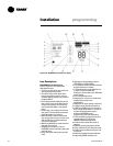
Unit Control Components
The Modular Series IntelliPak
self-
contained unit is controlled by a
microelectronic control system that
consists of a network of modules. These
modules are referred to as unit control
modules (UCM). In this manual, the
acronym UCM refers to the entire control
system network.
These modules perform specific unit
functions using proportional/integral
control algorithms. They are mounted in
the unit control panel and are factory
wired to their respective internal compo-
nents. Each module receives and
interprets information from other unit
modules, sensors, remote panels, and
customer binary contacts to satisfy the
applicable request; i.e., economizing,
mechanical cooling, heating, ventilation.
Following is a detailed description of each
module’s function.
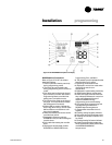
RTM Module Board - Standard
on all Units
The RTM responds to cooling, heating,
and ventilation requests by energizing the
proper unit components based on
information received from other unit
modules, sensors, remote panels, and
customer supplied binary inputs. It
initiates supply fan, exhaust fan, exhaust
damper, inlet guide vane positioning or
variable frequency drive output, and
airside economizer operation based on
that information.
Reference the RTM points list.
Note: Emergency stop and external auto/
stop, stop the unit immediately, emergency
stop generates a manual reset diagnostic
that must be reset at the unit human
interface. External auto-stop will return the
unit to the current operating mode when
the input is closed, so this input is auto
reset.
RTM Remote Economizer Minimum
Position
The remote minimum position
potentiometer, BAYSTAT023A, provides
a variable resistance (0-270 ohms) to
adjust the economizer minimum position
from 0 to 100% when connected to the
economizer remote minimum position
input of the RTM. The RTM must be
selected as the source for economizer
minimum position. If the RTM is the
selected source for economizer minimum
position, and
if a valid resistance per
Table O-GI-1 is provided to the RTM
remote minimum position input,
the OA
cfm compensation function will not
operate, even if enabled. “Default” is the
only possible source for economizer
minimum position when using the OA
cfm compensation function.
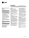
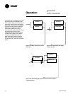
Table O-GI-1. Economizer remote minimum
position input resistance
input economizer
resistance min. position
0 - 30 ohms 0 %
30 - 240 ohms 0-100 % (linear)
240 - 350 ohms 100 %
> 350 ohms N/A *
* Note: A resistance greater than 350 ohms is
assumed to be an open circuit. The system will use
the default minimum position value.
RTM Analog Outputs
The RTM has two 0-10 vdc outputs: one
for the inlet guide vane option and one for
the economizer option. These outputs
provide a signal for one or two damper
actuators. There are no terminal strip
locations associated with these wires.
They go directly from pins on the RTM
circuit board to the actuator motor.
RTM Binary Outputs
The RTM has an output with pressure
switch proving inputs for the supply fan.
There is a 40 second delay from when
the RTM starts the supply fan until the fan
proving input must close. A fan failure
diagnostic will occur after 40 seconds.
This is a manual reset diagnostic, and all
heating, cooling, and economizer
functions will shut down. If this proving
input is jumped, other nuisance
diagnostics will occur. If the proving input
fails to close in 40 seconds, the
economizer cycles to the minimum
position. This is a manual reset
diagnostic. External control of the fan is
not recommended.
VAV Drive Max Output
This is a single-pole, double-throw relay
rated at a maximum voltage of 24 vac,
two amps. The relay contacts of this relay
switch when theunit goes from the
occupied mode to the unoccupied mode
bymeans of the occupied binary input.
The contacts will stay switched during the
unoccupied and morning warmup mode.
They will return to the position shown on
the unit wiring diagram when the unit
returns to the occupied mode. This binary
output signals the VAV boxes or other
terminal devices to go full open.
RTM Alarm Relay
This is a single pole, double throw relay
rated at a maximum voltage of 24 vac,
two amps max. Relay contacts can be
programmed from the unit human
interface. This relay can be programmed
to pick up on any one or group of
diagnostics from the unit human
interface.
Status/Annunciator Output
The status annunciator output is an
internal function within the RTM module
on CV and VAV units. It provides:
a. diagnostic and mode status signals to
the remote panel (LEDs) and to the
Human Interface.
b. control of the binary alarm output on
the RTM.
c. control of the binary outputs on the
GBAS module to inform the customer
of the operational status and/or
diagnostic conditions.
Occupied/Unoccupied Inputs
There are four ways to switch to
occupied/unoccupied:
1. Field-supplied contact closure
hardwired binary input to the RTM
2. Programmable night setback zone
sensor
3. Tracer Summit
4. Factory-mounted time clock
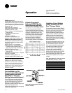
VAV Changeover Contacts
These contacts are connected to the RTM
when daytime heating on VAV units with
internal or external hydronic heat is
required. Daytime (occupied) heating
switches the system to a CV unit
operation. Refer to the unit wiring
diagram for the field connection terminals
in the unit control panel. The switch must
be rated at 12 ma @ 24 VDC minimum.
External Auto/Stop Switch
A field-supplied switch may be used to
shut down unit operation. This switch is a
binary input wired to the RTM. When
opened, the unit shuts down immediately
and can be cancelled by closing the
switch. Refer to the unit wiring diagrams
(attached to the unit control panel) for
proper connection terminals. The switch
Operation
general
information