


SCXG-SVX01B-EN 45
pre-startup
requirements
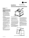
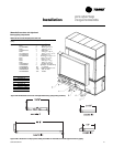
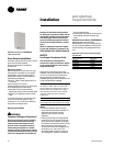
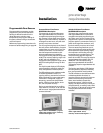
Figure I-PR-12. BAYSENS073
Zone temperature sensor w/timed override ,
accessory model number digit 6 = B
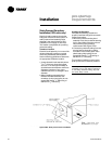
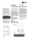
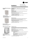
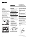
Figure I-PR-11. BAYSENS074
Zone temperature sensor w/timed override
and local setpoint adjustment,
accessory model number digit 6 = C
Integrated Comfort
™
Systems Sensors for CV and VAV
Applications
These zone sensor options are for use with cooling/heating Integrated Comfort System
(ICS) systems.
BAYSENS074 Description
This electronic analog sensor features single setpoint capability and timed override
with override cancellation.
BAYSENS074 features and system control functions include:
• Remote temperature sensing in the zone
• A timed override button to move an ICS or a building management system from its
“unoccupied” to “occupied” mode.
• Thumbwheel for local setpoint adjustment
• A cancel button to cancel the “unoccupied override” command.
(Possible Schematic Designation: 5U23)
BAYSENS073 Description
This electronic analog sensor features single setpoint capability and timed override
with override cancellation. It is used with a Trane Integrated Comfort
system.
BAYSENS073 features and system control functions include:
• Remote temperature sensing in the zone
• A timed override button to move an ICS or a building management system from its
“unoccupied” to “occupied” mode.
• Cancel button to cancel the “unoccupied override” mode.
(Possible Schematic Designation: 5U23)
CV and VAV Unit Zone Sensor
Options
Installation
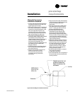
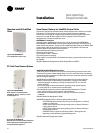
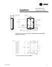
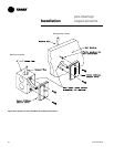
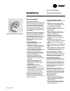
Figure I-PR-9. BAYSENS021
Single setpoint sensor with system
function lights, accessory model number
digit 6 = H
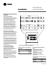
BAYSENS021 Description
This zone sensor module is for use with VAV units without night setback. It allows the
user to control system operation and monitor unit operating status from a remote
location. The sensor has a system switch, a S/A temperature setpoint indicator, a local
sensor, and four LED’s.
BAYSENS021 features and system control functions include:
• Temperature sensing in the zone
• System control switch with mode setting for "AUTO" and "OFF"
• Supply air single temperature setpoint
• Function status indicator lights:
“SYS ON” glows continuously during normal operation, or blinks if system is in
test mode.
“COOL” glows continuously during cooling cycles, or blinks to indicate a
cooling system failure.
“HEAT” glows continuously during heating cycles, or blinks to indicate a
heating system failure.
“SERVICE” blinks or glows to indicate a problem. These signals vary
depending on the particular equipment being used.
(Possible Schematic Designation: 5U25)
VAV Unit Zone Sensor Option