


72 SCXG-SVX01B-EN
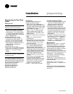
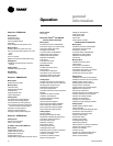
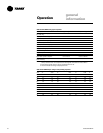
Table O-GI-2. RTM sensor resistance vs. temperature
temperature, °F resistance, Ω ohms temperature, °F resistance, Ω ohms
-40 346.1 71 11.60
-30 241.7 72 11.31
-20 170.1 73 11.03
-10 121.4 74 10.76
-5 103.0 75 10.50
0 87.56 76 10.25
5 74.65 77 10.00
10 63.8 78 9.76
15 54.66 79 6.53
20 46.94 80 9.30
25 40.40 85 8.25
30 34.85 90 7.33
35 30.18 100 5.82
40 26.22 105 5.21
45 22.85 110 4.66
50 19.96 120 3.76
55 17.47 130 3.05
60 15.33 140 2.50
65 13.49 150 2.05
66 13.15 160 1.69
67 12.82 170 1.40
68 12.50 180 1.17
69 12.19 190 0.985
70 11.89 200 0.830
general
information
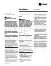
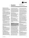
Table O-GI-4. RTM resistance value vs. system operating mode
resistance
applied to RTM mode
CV units VAV units
input terminals, ohms fan mode system mode system mode
2320 auto off off
4870 auto cool
7680 auto auto auto
10,770 on off
13,320 on cool
16,130 on auto
19,480 auto heat
27,930 on heat
Note: Mode boundaries are 1000 to 40,000 ohms. Other boundaries are equal to the midpoint between the
nominal mode resistance.
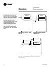
Table O-GI-3. RTM setpoint analog inputs
cooling or heating setpoint input, °F cooling setpoint input, °F
(using RTM as zone temp. source) (using RTM as supply air temp. source) resistance, Ω
ohms
40 40 1084
45 45 992
50 50 899
55 55 796
60 60 695
65 65 597
70 70 500
75 75 403
80 80 305
NA 85 208
NA 90 111
must be rated for 12 ma @ 24 VDC
minimum. This input will override all VOM
inputs, if the VOM option is on the unit.
Occupied/Unoccupied Contacts
To provide night setback control if a
remote panel
with night setback
was not
ordered, install a field-supplied contact.
This binary input provides the building’s
occupied/unoccupied status to the RTM. It
can be initiated by a time clock, or a
building automation system control
output. The relay’s contacts must be rated
for 12 ma @ 24 VDC minimum. Refer to
the appropriate wiring diagrams
(attached to the unit control panel for the
proper connection terminals in the unit
control panel.
Emergency Stop Input
A binary input is provided on the RTM
board for installation of a field-supplied
normally closed (N.C.) switch to use
during emergency situations to shut
down all unit operations. When open, an
immediate shutdown occurs. An
emergency stop diagnostic enters the
human interface and the unit will require
a manual reset. Refer to the unit wiring
diagrams (attached to the unit control
panel for the proper connection
terminals. The switch must be rated for
12 ma @ 24 VDC minimum. This input
will override all VOM inputs, if the VOM
option is on the unit.
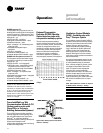
VAV Box Option
To interlock VAV box operation with
evaporator fan and heat/cool modes,
wire the VAV boxes/air valves to VAV box
control connections on the terminal block.
Supply Duct Static Pressure Control
The RTM relies on input from the duct
pressure transducer when a unit is
equipped with IGV or VFD to position the
IGV or set the supply fan speed to
maintain the supply duct static pressure
to within the static pressure setpoint
deadband.
RTM Sensors
RTM sensors include: zone sensors with
or without setpoint inputs and modes,
supply air sensor, duct static pressure,
outside air temperature, outside air
humidity, airflow proving, and dirty filter.
Operation